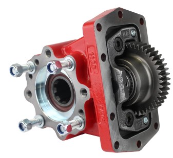
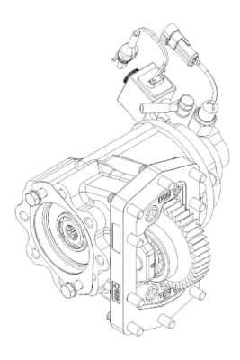
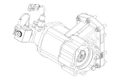
Compatible with the most common transmissions in the market. The 3940 series PTOs feature a wide range of input gear, ratio, output, and shifter options. All cast iron construction with large 12mm flange bolts to support some of the larger pumps in the market.
Features and benefits:
- Unique hot shift unit that offers a DIN 5462 output shaft option as standard.
- Special design, allowing a variety of output adapter options.
- Deep gear tooth carburization for longer gear life.
- Larger flange mounting hardware provides additional support and reduces failures caused by heavy pumps – best in class.
- Industry leading Garlock gasket material provides better tear resistance and easier installation, with Viton o-ring material & shaft seals to prevent leaks.
- Clutch pack material is designed to provide smooth engagement and long life.
- Quiet operational noise levels for an improved operator experience.
Competitive with:
- Chelsea 210
- Muncie F20
Torque ratings: up to 230 lb. ft.
Typical Applications: Dump Trucks and Trailers, Walking Floor, Low Boy, Vacuum Pumps, and more…..
CAUTION
TO PREVENT POSSIBLE INJURY:
- DO NOT go underneath the vehicle with the engine running.
- DO NOT attempt to work on an installed Power Take-Off with the engine running.
- DO NOT operate the controls of the Power Take-Off or other driven equipment from underneath the vehicle with the engine running.
- DO NOT operate the controls of the Power Take-Off or other driven equipment in any position that could result in getting caught in the moving machinery.
Make sure to block any moving or raised device that may injure a person working on or under the truck. A lever or its linkage may be accidentally moved causing movement of the device which could cause injury to a person near the device.
IMPORTANT
Because most of our Bezares Power Take–Offs and P.T.O. drive lines are sold through distributors, the product applications and the resulting degree of exposure to danger of the operators are beyond the knowledge and controls of BEZARES.
Therefore, the proper installation of the P.T.O. and its associated equipment, and the decisions of whether to install guards and/or warning signs shall be the responsibility of the designers or installers.
Since it is our major objective to show you how to get additional and more profitable miles from truck, tractor and trailer components, we want to provide you with information on the installation of 3940 Series.
We all realize that an inadequate transmission will overwork any Power Take–Off in a very short period of time. In addition, a mismatched transmission/P.T.O. combination can result in unsatisfactory performance of the equipment right from the start.
Before you order new trucks be sure that you’re getting the right transmission/P.T.O. combination. It is of vital importance for efficient performance to have adequate power.
To help you select the proper type, size and design of P.T.O. it is advisable to discuss your specific requirements with a Bezares P.T.O. specialist. They know their products and Power Take–Offs. They can inform you about everything you need to know about power, at the right time, before you specify components.
Here are some of the questions that are relevant to the Proper Selections of a Transmission mounted Power Take–Offs.
- What is the make and model of your transmission?
- Which P.T.O. opening will be used?
- What accessory is to be driven?
- How much horsepower is required to drive the accessory?
- What is the required rotation of the P.T.O.?
- What is the required P.T.O. output shaft speed as a percent of engine speed?.
- What is the required method of shifting the P.T.O., mechanical or pneumatic?
Once all of the answer to these questions have been determined, a transmission mounted P.T.O. can be selected to meet the horsepower, speed and rotation that you require.
Check out our PTO Selection form at bezares.com/pto-selection-tool/
Having made the selection of a P.T.O., you are ready to start the installation.
step 1: With Park brake set, place truck in neutral and start engine.
Listen to engine and transmission Any transmission, gear noise may be more noticeable after PTO is installed which is caused by Torsional vibrations.
STOP ENGINE-Never go under truck with engine running!
step 2: If chassis is 4X4 remove or disconnect driveshaft for clearance
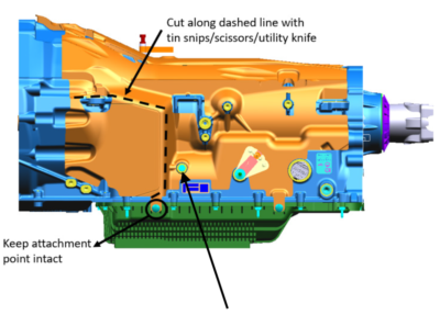
step 3: Find PTO opening on transmission.
If applicable remove NVH (Noise-Vibration-Heat) material from area around PTO aperture.
The NVH will need to be cut from shaded area shown or compress for PTO clearance.
See Ford SVE Service Bulletin Q-300 available at (www.fordbbs.com)
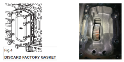
step 4: Remove the ten bolt aperture cover, placing a drain pan below for any drainage.
Discard factory gasket.
Note: transmission PTO drive gear must be present
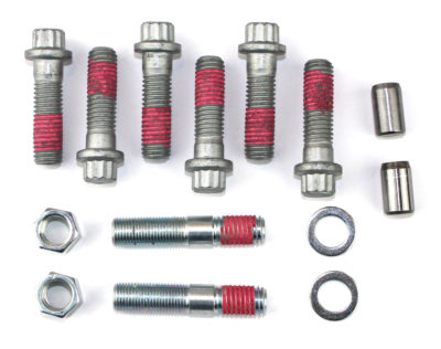
Note: Mounting kit contains 2 guide pins-6 cap screws and 2 step studs with washers and nuts
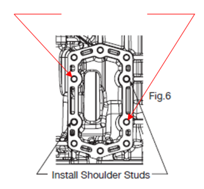
step 6: Install guide pins in location shown hole postion 4 & 10. Install step studs in location 2 & 8
CAUTION! If installing on a Gas Engine powered chassis: Prior to PTO installation, wrap exhaust down pipe with heat refective material. Exhaust header pipe wrap may be used or an aftermarket heat shield. It is also necessary to install reflective loom or heat protection sleeve on pressure switch wires as well as wiring to coil.
Caution
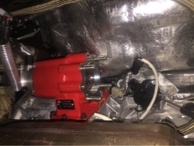
step 8: Mount PTO using the six cap screws plus 2 washers and nuts on step studs. Torque to 28 lb. ft.
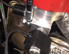
step 9: Install pressure switch inside port and solenoid valve on end port per picture. Place a dab of Loctite Blue on valve nut. Make sure that the O’ring is installed prior to attaching nut
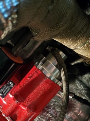
step 10: Install pressure hose in pressure activation port as shown above. Caution! If chassis has a gas engine, Install heat resistant loom over pressure supply hose. See picure below.

step 11: Heat resistant header pipe wrap- with clamps.
1. Read and follow the truck’s manual before attempting to run PTO
2. Verify transmission has adequate fluid and extra fluid to compensate for PTO
(DO NOT OVER FILL)
3. Follow all company, federal, state and local safety procedures and guidelines.
4. Apply parking brake.
5. Truck must be in neutral.
6. Insert key in ignition.
7. Verify no one is under vehicle or near any rotating parts – ALL CLEAR!
8. Start engine, the PTO is not engaged, and the output shaft is not turning.
9. Depress the in-dash PTO #1 rocker switch, it will illuminate, the engine rpm
slightly increases.
10. The PTO now shifts, and the output shaft is rotating.
11. Depress the PTO rocker switch to disengage PTO and discontinue output shaft
rotation.
1. Check for leaks, fix any if found.
2. After truck warms up check all hardware for proper torque, tighten as needed.
3. Check all wire connections, ensure they are correctly installed and away from
heat and rotating parts, fix and repair as needed.
4. Check the airline, ensure it is correctly installed and away from heat and
rotating parts, fix and repair as needed.
The PTO is installed. Complete the rest of the associated equipment installation
CAUTION
This vehicle is equipped with a Power Take-off.
Shut engine off before working on Power Take-Off or getting below vehicle.
Consult operating instructions before using.
POWER TAKE-OFF OPERATION VEHICLE STATIONARY.
- Mechanical Transmission.
A power take-off is, and should be, operated as an integral part of the main transmission.
Before shifting the power take-off into or our of gear, disengage the clutch and wait for transmission or P.T.O. gears to stop rotating. - Automatic transmission with manual shift P.T.O. (Includes air shift).
On automatic transmissions, the gears in the transmission turn when the transmission is in neutral, therefore, gear clashing will ocurr if the power take-off is shifted into gear at this time.
With converter driven gear:
• Shift transmission lever into any of drive positions. (This will stop the transmission gear from turning).
• Shift power take-off into gear.
Shift transmission into neutral. (This will start transmission gears turning.)
• Shift P.T.O. into gear before starting engine.
This procedure should eliminate gear clash. - Automatic transmission with power shift P.T.O’s
Engage P.T.O. with engine at idle speed. Power shift P.T.O.´s: engine must be at idle when P.T.O. is engaged. See transmission manufacture´s instructions for special procedures.
IMPORTANT
Failures to follow proper shifting or operating sequences will result in premature P.T.O. failure with possible damage to other equipment.
GENERAL INFORMATION
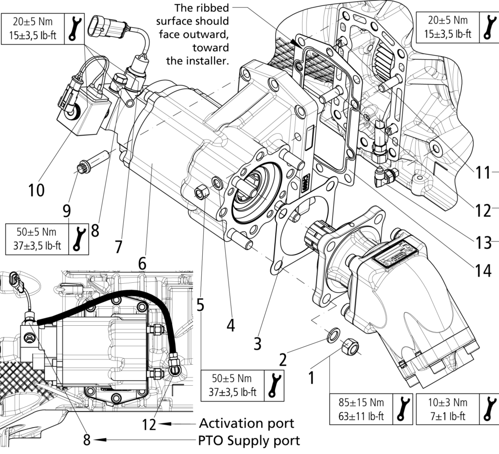
The following installation instruction for fitment of the conversion kit to PTO 3940 (part no.-
806635, 806735, 806835) should be followed in order to ensure good performance and long life. Where it is obvious that this instructions have not been followed, then warranty claims will not be accepted.
INSTALLATION METHOD
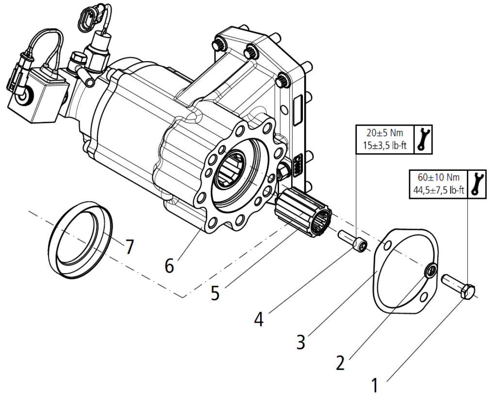
First, remove the adapter bush (7) to the PTO housing (6).
Next, mounting the adapter hub (5) to the PTO housing (6) and thread the Screw M8 (4)
in accordance with the torque shown in the figure.
Finally, fit a gasket (3) between pump and PTO housing, apply pressure on screws (1) and
their washers (2) in accordance with the torque shown in the figure.
| Items | Description |
|---|---|
| 1 | Screw |
| 2 | Washer |
| 3 | Gasket |
| 4 | Screw M8 |
| 5 | Adapter Hub |
| 6 | PTO Housing |
| 7 | Adapter Bush |
Before you order new trucks be sure that you’re getting the right transmission/P.T.O. combination. It is of vital importance for efficient performance to have adequate power. To help you select the proper type, size and design of Pump it is advisable to discuss your specific requirements with a Bezares P.T.O. specialist. They know their products and Power Take–Offs. They can inform you about everything you need to know about power, at the right time, before you specify components.
step one
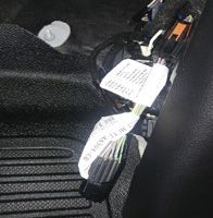
Locate the 2020 Ford wires bundled together at the Passenger Side located behind the kick panel at the passenger’s feet.
step two
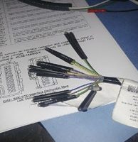
Remove the bundled wires from the two-sided connector (female pins)
step three
Strip the selected wire ends and install butt connectors.
Bezares to Ford (diesel) colored wiring
| => | Green- CE914-(PTO RPM) | Pin 9 |
| => | White/Brown LE434-(DIESEL PTO VREF) | Pin 10 |
| => | Gray/Violet- RE327-(DIESEL PTO RTN) | Pin 6 |
| => | Blue/White- CE326-(PTO RLY) | Pin 4 |
| => | Yellow/Green- CE912 (STATIONARY) | Pin 7 |
| => | OR Blue/Orange- CE933 (MOBILE) | Pin 11 | |
| => | 12V switched for customer supplied PTO indicator light. | |
| => | Pressure switch ground loop for customer supplied PTO indicator light. | |
| => | Auxiliary Upfitter switch # 1 CB117 – Brown/Green | |
| => | BATTERY GROUND |
Split shaft mode • Diesel
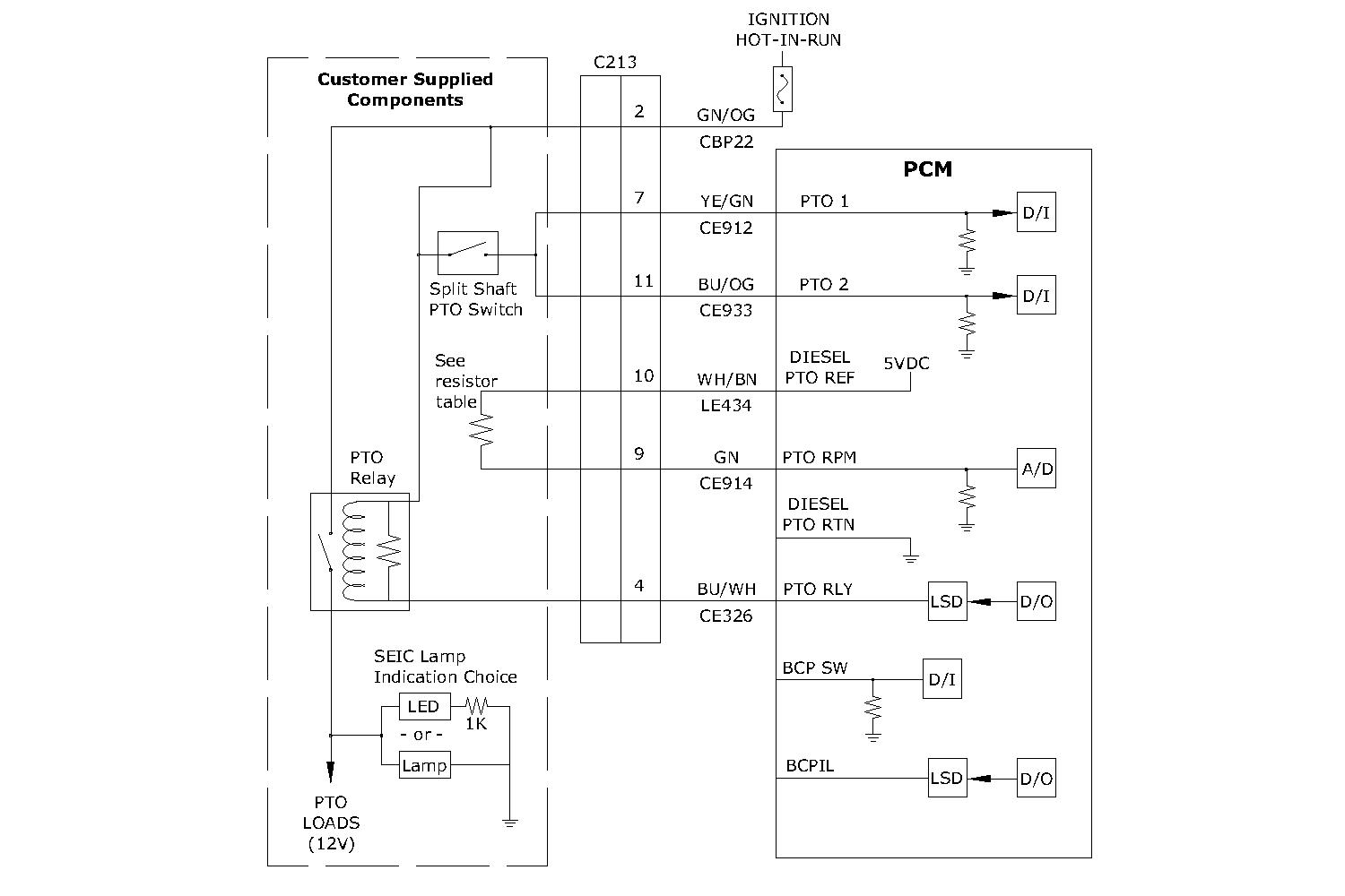
SEIC – PTO Enable / Disable conditions
| Vehicle Conditions to Enable SEIC (all are required) | Vehicle Conditions that Disable SEIC (any one required) | SEIC | Split-Shaft (Diesel Only) | Mobile Mode |
|---|---|---|---|---|
| Parking brake applied | Parking brake disengaged | Yes | Yes | No |
| Foot off service brake | Service brake depressed | Yes | Yes | No |
| Vehicle in Park | Vehicle taken out of Park | Yes | Yes | No |
| Foot off accelerator pedal | Accelerator pedal depressed | Yes | Yes | No |
| Vehicle speed is 0 MPH (stationary) | Vehicle speed is not 0 MPH | Yes | Yes | No |
| Engine at a stable base idle speed | — | Yes | Yes | No |
| Transmission oil temp above 20ºF | Transmission oil temperature exceeds 240ºF (Diesel) or 250ºF (Gas) | Yes | Yes | Yes |
| Engine coolant termperature at least 20ºF (6.7L Diesel) | Engine coolant temperature exceeds 230ºF | Yes | Yes | Yes |
| Engine coolant termperature at least 20ºF (6.2L or 7.3L Gas) | Engine coolant temperature exceeds 230ºF | Yes | N/A | Yes |
| — | Catalist temperature limit | Yes | Yes | Yes |
BEZARES to FORD SEIC Circuit Wiring- 2020/2021
10R140-6.2-7.3L-GAS- F250-600
| => | Green- CE914-(PTO RPM) | Pin 9 |
| => | Yellow/Green- LE424-(PTO VREF) | Pin 18 |
| => | Yellow/Violet- RE407-(SIGNAL RETURN C) | Pin 16 |
| => | Blue/White- CE326-(PTO RLY) | Pin 4 |
| => | Yellow/Green- CE912 (STATIONARY) | Pin 7 |
| => | OR Blue/Orange- CE933 (MOBILE) | Pin 11 | |
| => | 12V switched for customer supplied PTO indicator light. | |
| => | Pressure switch ground loop for customer supplied PTO indicator light. | |
| => | Auxiliary Upfitter switch # 1 CB117 – Brown/Green | |
| => | BATTERY GROUND |
| Note! When using the Auxiliary Upfitter Switch # 1, the pressure switch port may be plugged. This will eliminate a PTO indicator light. If a true PTO indicator light is desired the upfitter can install their own indicator light. This requires the Pressure Switch to be installed in PTO rear cover. Connect the Pressure Switch ground loop (purple) wire and the 12 V switched (red) wire to customer supplied PTO indicator light |
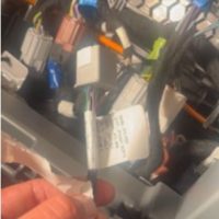
1- Locate the SEIC wiring connector located behind and below the passenger side glove box. The glove box will require some disassembly.

2- Strip the sealed end from the required color-coded wires. See following charts for wire selection.
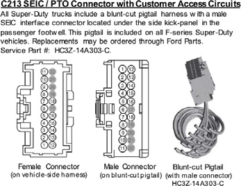
SEIC/PTO CONNECTOR WITH CUSTOMER ACCESS CIRCUITS
All Super duty trucks include a blunt cut pigtail harness with female SEIC interface connector located under the side kick-panel in the passenger footwell. This pigtail is included on all F-Series Super Duty vehicles.
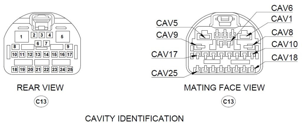
Bezares to Ford Circuit Wiring (6.7 diesel) F250-600 May 2023 & later
| => | Green/White- VE925-(PTO RPM) | Pin 5 |
| => | White/Brown LE434-(DIESEL PTO VREF) | Pin 3 |
| => | Gray/Violet- RE327-(DIESEL PTO RTN) | Pin 4 |
| => | Blue/White- CE326-(PTO RLY) | Pin 6 |
| => | Yellow/Green- CE912 (STATIONARY) | Pin 7 |
| => | OR Blue/Orange- CE933 (MOBILE) | Pin 8 | |
| => | 12V switched for customer supplied PTO indicator light. | |
| => | Pressure switch ground loop for customer supplied PTO indicator light. | |
| => | Auxiliary Upfitter switch # 1 CB117 – Brown/Green | |
| => | BATTERY GROUND |
| Note! When using the Auxiliary Upfitter Switch # 1, the pressure switch port may be plugged. This will eliminate a PTO indicator light. If a true PTO indicator light is desired the upfitter can install their own indicator light. This requires the Pressure Switch to be installed in PTO rear cover. Connect the Pressure Switch ground loop (purple) wire and the 12 V switched (red) wire to customer supplied PTO indicator light |
Bezares to Ford Circuit Wiring (6.2-7.3 Gas) F250-600 May 2023 & later
| => | Green/White- VE925-(PTO RPM) | Pin 5 |
| => | White/Brown LE424-(PTO VREF) | Pin 3 |
| => | Gray/Violet- RE327-(PTO SIGNAL RETURN C) | Pin 4 |
| => | Blue/White- CE326-(PTO RLY) | Pin 6 |
| => | Yellow/Green- CE912 (STATIONARY) | Pin 7 |
| => | OR Blue/Orange- CE933 (MOBILE) | Pin 8 | |
| => | 12V switched for customer supplied PTO indicator light. | |
| => | Pressure switch ground loop for customer supplied PTO indicator light. | |
| => | Auxiliary Upfitter switch # 1 CB117 – Brown/Green | |
| => | BATTERY GROUND |
| Note! When using the Auxiliary Upfitter Switch # 1, the pressure switch port may be plugged. This will eliminate a PTO indicator light. If a true PTO indicator light is desired the upfitter can install their own indicator light. This requires the Pressure Switch to be installed in PTO rear cover. Connect the Pressure Switch ground loop (purple) wire and the 12 V switched (red) wire to customer supplied PTO indicator light |
Auxiliary pto switch # 1- 25amp fused
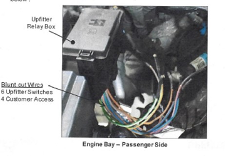
Connect the brown wire to the upfitter switch Green/Brown wire. The relay box is
located on the the passenger side of the firewall.
Six upfitter switch blunt-cuts (located underhood below upfitter relay box)
| Upfitter Switch | Fuse # | Wire Color | Circuit | Rating | Configuration |
|---|---|---|---|---|---|
| AUX 1 | F10 | BN/GN | CB117 | 25A | IGNITION HOT ONLY |
| AUX 2 | F9 | VT/OG | CB114 | 25A | IGNITION HOT ONLY |
| AUX 3 | F8 | BU/BN | CB116 | 25A | IGNITION HOT ONLY |
| AUX 4 | F7 | GY/BN | CB113 | 25A | IGNITION HOT ONLY |
| AUX 5 | F1 | BN/BU | CB115 | 40A | IGNITION HOT OR HOT-AT-ALL-TIMES |
| AUX 6 | F2 | GY/OG | CB118 | 40A | IGNITION HOT OR HOT-AT-ALL-TIMES |
Proper maintenance of your Power Takeoff (PTO) is crucial to ensure the longevity and optimal performance of your vehicle. Follow these tips to maintain your PTO:
Safety First: Do not go under or near PTO when the engine is running. Shut off the engine and disconnect batteries on electric motor-driven PTOs (i.e., hybrid vehicles) before checking or servicing.
Service Intervals: The PTO, being an integral part of the transmission, should be serviced at the same intervals as the transmission. Transmission fluid changes should follow the interval recommended by the vehicle manufacturer for severe service.
Check for Leaks: Checking for PTO leaks and checking the transmission oil level should be done regularly. Loss of oil can significantly affect or damage the transmission. Check for leaks upon delivery of the vehicle and after initial operation of equipment.
Maintenance Checks: The PTO requires periodic checks. Typically, the interval for maintenance checks of the PTO depends on the application of the vehicle. For severe-duty PTO applications, it is recommended that the PTO be checked for service every 100 hours of use (this guideline can be adjust-ed based on past service history once you have it established). Service should include checking and lubricating direct-mount pump shaft connections on a regular basis.
Recheck the Installation: Within the first week of use, recheck the installation of the PTO. Check for leaks in air lines or hydraulic connections with air shift or hot shift PTO’s and loose mounting hardware (studs, cap screws, nuts). Recheck the cables or lever connections for proper adjustments and lubricate moving parts, tighten and repair ALL connections, hoses, mounting hardware, cable, and lever connections.
Visual Inspection: It is recommended that the operator/owner do a visual inspection for leaks under and around the vehicle and equipment before entering or starting the equipment on at least a weekly basis. Any leaks should be corrected immediately.
Anti-Seize or High-Temperature Grease: Pumps that are directly mounted to the PTO output require the application of anti-seize or a high-temperature, high-pressure grease (unless the PTO is a wet spline option). The purpose of this grease is to help make the PTO easier to service and to reduce the effects of fretting corrosion on the mating PTO and pump shafts. PTO’s under severe duty cycles and/or high torque requirements may require servicing of this pump shaft connection by periodically regreasing the shafts. Vehicles with low-speed engines are also considered severe duty applications due to the inherent vibrations of the vehicles. Fretting corrosion cannot be stopped by greasing the shafts; it is only a deterrent. Wet spline PTO’s do not require servicing this connection.
Remember, failure to comply entirely with the provisions set forth in the appropriate Owner’s Manual will result in voiding of ALL Warranty consideration.
For any queries, contact your equipment installer.

