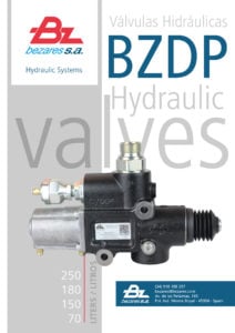
BZDP 180 1, 2 or 3 pressures, proportional tipping valve open circuit or close circuit, pneumatic operated, different relief valves. It also includes check valve and pull-push end of stroke. Pressure switch is optional.
IMPORTANT: Read this manual carefully and make sure you fully understand it before installing and using the tipper valve. The following signs are used in this manual according to the type of risk the operator faces:
WARNING
It is essential to insure proper function of Tipper Valve and your hydraulic system to check and verify that flow and working pressure are correct for each application and are with in Tipper Valve capability by using an accurate flow meter and pressure gauge.
Failure to do the above listed procedures will void Bezares product warranty.
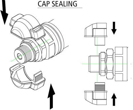
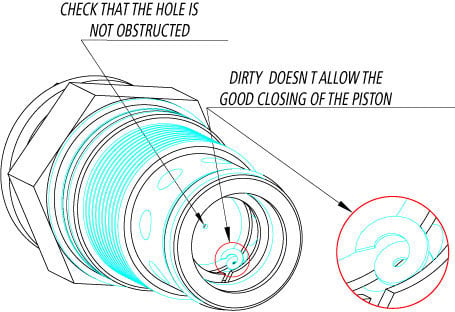
If the system does not get pressure, it is because of the relief valve is open. Unscrew the cartridge and check that there is no anything inside. Never set up the relief valve again without cleaning carefully the relief valve cartridge.
If you have any doubt about its use or the correct operation, please contact our closest distributor or our after-sales service.
IMPORTANT
The operator is solely responsible for safe installation and operation.
General safety recommendations
We recommed the use of open-center, instead of closed-center tipping valves as a passive safety measurement against the case of an accidental activation of the PTO or pump. In that case pressure flow will go directly to the tank and nothing more will happen.
Take in account a good hoses calculation in order to avoid heating or pressure drop problems. It will also help to enlarge the life of your hydraulic equipment”
BZDP 70L
BZDP 180L
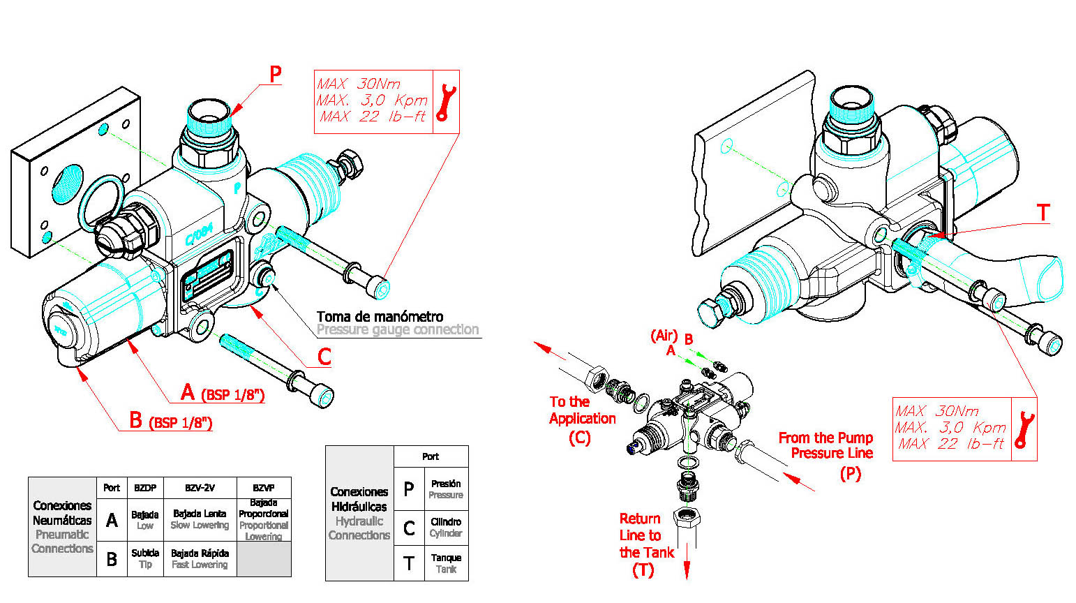
BZDP 150L
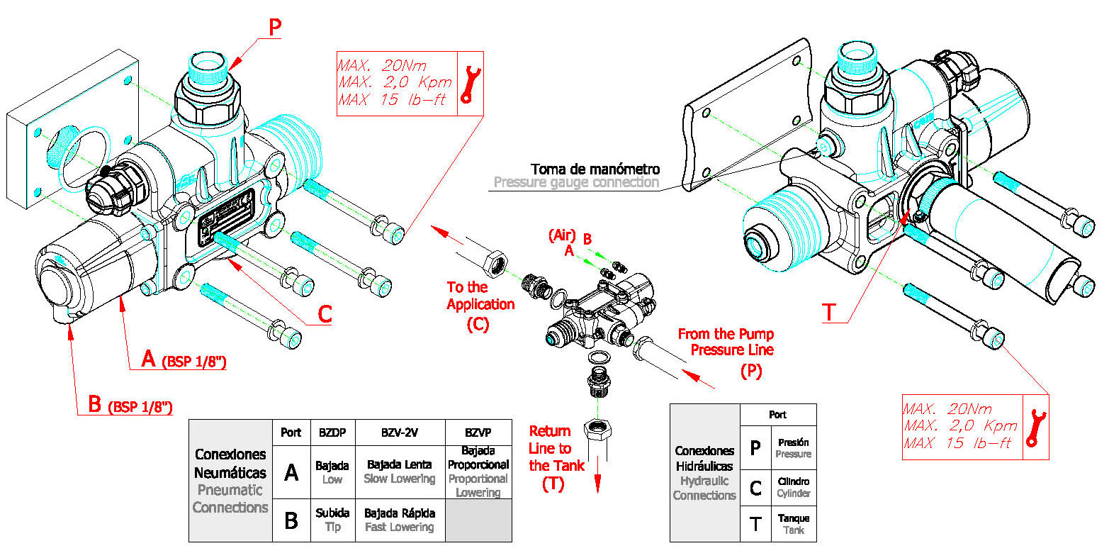
BZDP 250L
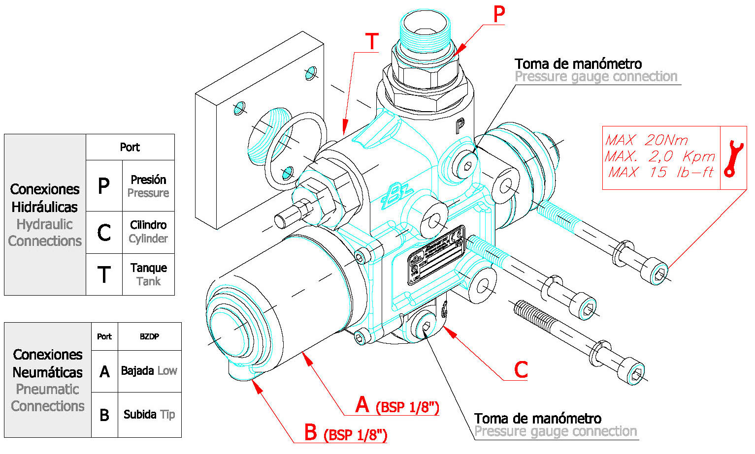
Valid for the models BZD 70/150/180/250, BZV 70/150/18.
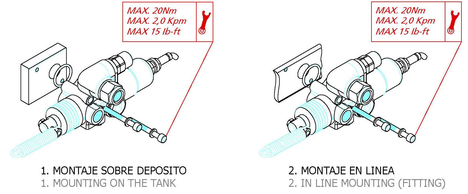
- Tipper Valve must be mounted on a flat surface of sufficient thickness to prevent any uneven stress to the tipper valve body when mounted and during operation, which includes allowing for gauge port clearance.
- If Tipper Valve is to be mounted to a surface which needs to be welded be sure there are no deformations to mating surfaces.
- When mounting Tipper Valve to mated surface install mounting bolts and lock nuts (2) and tighten to the corresponding torques specified in this manual.
- Verify smooth stroke of Tipper Valve spool thru its entire length of travel with a minimum of 6Bar (87 PSI) applied to the raise port and then lower port of the air cylinder located on the front of the tipper valve
- If Tipper Valve spool does not function properly loosen or remove valve from mount, check to be sure mating surfaces are mated properly, test Tipper Valve on bench. If Tipper Valve works properly, reattach and retest. If Tipper Valve still does not work properly contact the seller or local Bezares subsidiary.
If the system does not get pressure, it is because of the relief valve is open. Unscrew the cartridge and check that there is no anything inside. Never set up the relief valve again without cleaning carefully the relief valve cartridge.
Version /2 - (pilot operated) - P/N. 9072190
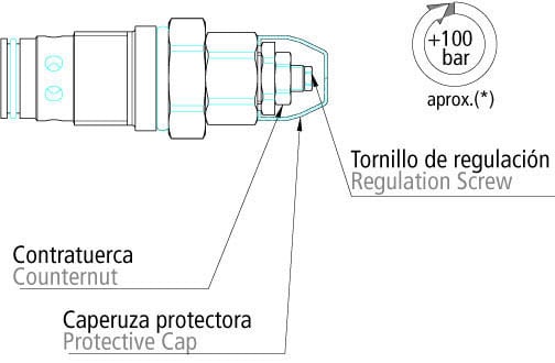
SETUP
- Remove the plastic cover.
- Unscrew the counternut
- Adjust the pressure with the regulation screw.
- Tighten the counternut and replace the plastic cover (take a new one)
Version /3 - (direct operated) - P/N. 9062990
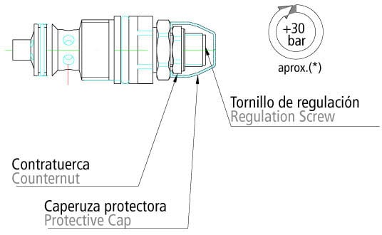
SETUP
- Remove the plastic cover.
- Unscrew the counternut.
- Adjust the pressure with the regulation screw.
- Tighten the counternut and replace the plastic cover (take a new one)
Setting instructions 9048490
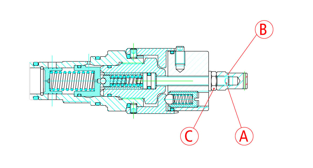
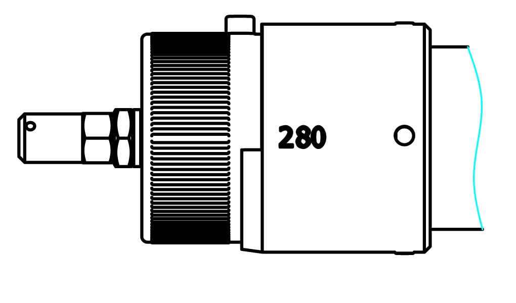
SETTING
- Remove the cupola nut (b) and loose the counternut (c)
- Rotate the pressure selector up to the maximum pressure. adjust by means of the allen stud (a) the maximum pressure desired
- Lock the allen stud (a) with the counternut (c). Thread again the cupola nut
PRESSURE RANGES
- 2 pressures relief valve: Approximate difference of 100 bar between both of them
- 3 pressures relief valve: Approximate difference of 70 bar between first and second. Approximate difference of 100 bar between second and third.
PNEUMATIC RELIEF VALVE 2 PRESSURES
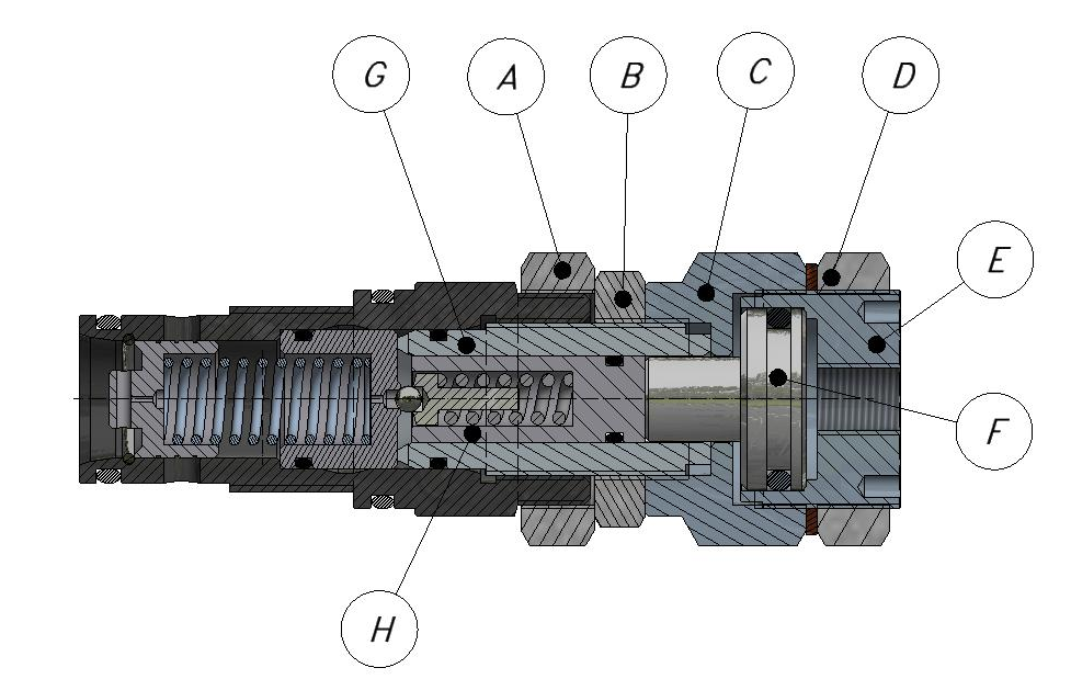
This cartridge has the possibility to be set at two different pressures, independently of the difference between both of them.
The operation of this cartridge is simple and easy.
ITEMS
- Lock Nut. Locks nut (B) into position.
- Lock Nut. Locks the High-Pressure Regulator (C) into position.
- High Pressure Regulator sets high pressure when piston (F) isn’t allowed to stroke between (C) and (E).
- Lock Nut. Locks (C) and (E) into position when low pressure has been set.
- Threaded Low-Pressure Cylinder. This piece sets the low pressure.
- High Pressure Piston.
- Threaded Dampening Piston Guide
- Dampening Piston
SETTING
- Partially unscrew the lock nut (D). This will leave Threaded Low-Pressure Cylinder (E) loose to allow for adjustment.
- Adjust, tighten (E) until it stops. This will compress (C)-(F)-(E).
- With pressure in the hydraulic circuit, set the higher pressure by tighten or loosening all 3 components (C)-(F)-(E) as one assembly.
- Lock the assembly into position with (B).
- Tighten Lock nut (A) to Lock Nut (B), maintaining position of (B)-(C)-(D)-(E).
- Loosen part (E) slightly to adjust the lower pressure setting.
- Fix (E) with the nut (D).
Now the cartridge is ready to be operated at two different pressures
Valve with air pressure must be between 6 bar (90 PSI approx) and 9 bar (130PSI approx). The valve must be air operated only when working with the high pressure setting.
- This cartridge has the possibility to be set to two different pressures regardless of the difference between them.
- The operation of this cartridge is simple and easy.
- It is available in different pressure settings depending on the code and color of the cartridge.
- To select the high-pressure mode, the valve must be air operated (between 6 and 10 bar, 90 – 140 psi).
- Set screw. It blocks the nut 15.
- Nut. It limits the maximum pressure of the high-pressure regulator 17.
- Nut. It blocks the high-pressure regulator
- High-pressure regulator.
- Piston. It compresses the adjustable spring of the relief valve.
- Nut. It blocks the high-pressure 17 and the low-pressure regulator 21 position.
- Low-pressure regulator.
Code
High pressure setting
Low pressure setting
9079190
140 bar / 2030 psi
210 bar / 3045 psi
9079190-1
160 bar / 2320 psi
350 bar / 5070 psi
9079190-2
160 bar / 2320 psi
250 bar / 3620 psi
- Loosen the nut 20 to set free the low-pressure regulator 21.
- Tighten the low-pressure regulator 21 against the high-pressure regulator 17 to make a block 17-18-21.
- Loosen the nut 16 to set free the block 17-18-21.Adjust the block 17-18-21 to set the high-pressure value.
- Fix* the block 17-18-21 with the nut 16. Installation torque between 40 – 45 Nm (30 – 33 Lb*ft).
- Loosen the low-pressure regulator 21 to set the low-pressure value.
- Block* the low-pressure regulator 21 with the nut 20. Installation torque between 60 – 70 Nm (44 – 51 Lb*ft).
* Use Loctite 270 threadlocker
OBSERVATIONS
- Approximately, each turn of the low-pressure and high-pressure regulator increases the pressure by 140 bar (2030 psi).
- Maximum working pressure (350 bar – 5070 psi) is reached when the high-pressure regulator 17 is tightened against the nut 15.
- Nut 15 helps to limit the relief valve maximum pressure by preventing the high-pressure regulator 17 to be tightened until the end of the thread. Please, do not manipulate the set screw 14 or the nut 15.
DUMP
- Engage PTO. Listen for pump to engage.
- Be sure high-pressure valve is in the low-pressure position
- Ensure either tractor or trailer brakes are released if working with a frameless trailer
- Go to “Raise” position of cab control
- Using cruise control to increase engine RPM to specified RPM
- Raise bed, then lower RPM when operating last stage, move incab control to “Hold” before dump cylinder reaches end of travel.
- Move in cab control to “Lower” to lower dump bed.
WALKING FLOOR
- Engage PTO. Listen for pump to engage.
- Be sure high-pressure valve is in the low-pressure position.
- Go “Raise” position of cab control.
- Position high pressure valve in the high-pressure position.
- Use cruise control to increase engine RPM to specified RPM when trailer is off loaded
- Move high pressure valve to the low pressure position
- Return cab control to neutral position
- Disengage PTO
Use mineral based oils for hydraulic systems. To select the correct viscosity, the operating temperature of the oil, measured in the tank should be considered. At operating temperature, the viscosity of the oil should be within the range of 20-35 cSt. Maximum temperature at any point in the system must be less than 90ºC.
Please, use the following guidelines to choose the correct oil grade: 20-40ºC: VG 22 – VG 32; 40-60ºC: VG 32 – VG 46; 60-90ºC: VG 68 – VG 100
The finer the filtration, the better the achieved purity grade of the fluid, and the longer the life of the system. Purity grades of 18/13 (ISO 4406) or 9 (NAS 1638) should be guaranteed by the filtration system. We suggest a return filter, (avoid a filter in the suction line) with a mesh from 10 µm (high pressure and/or contaminated environment) to 25 µm (low pressure and clean environment).
If the system does not get pressure, it is because of the relief valve is open. Unscrew the cartridge and check that there is no anything inside. Never set up the relief valve again without cleaning carefully the relief valve cartridge.
Warranty information
All of our products are guaranteed against all manufacturing faults. The guarantee for use will be understood as for one year commencing from the date of the dispatch of the goods, with the reservation that the guarantee will depend on the treatment that the goods had received and will only be valid with a necessary report from our Technical Service Department.
The manufacturer will not be liable to pay any compensation for loss of profits or losses brought about by product defects beyond that stated in this same point in regard to the guarantee.
Returnings
In order to make any return of goods we must be advised in advance. Our warehouses will not accept any despatch of returned goods that are sent “Carriage Due” and/or not authorised by BEZARES, S.A. Returns will not be accepted after 30 days from the date of the delivery note.
- All returned materials will be inspected by the materials reception department to decide on their state.
- The material must be completely new, without having been used and that is currently on sale, this being that it is not obsolete.
- It is absolutely necessary that any return is previously informed, and authorized by Bezares’s After-sales Department. Each package has to include inside, complete documentation explaining the reasons of the return, and the sticker outside, showing us “RETURN”. The forms and the stickers are included inside the packing of all Bezares products.
- Consult refunds policies with our customer service department.
Liability
Bezares, S.A. will not be held liable under any circumstances for their use or the defective assembly of its products, for breakdowns caused by external agents, excessive loads, inadequate lubrication, defects that may appear in the fitting of gear boxes to used vehicles, or for any other cause or accident outside of its control.
