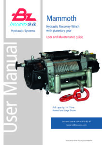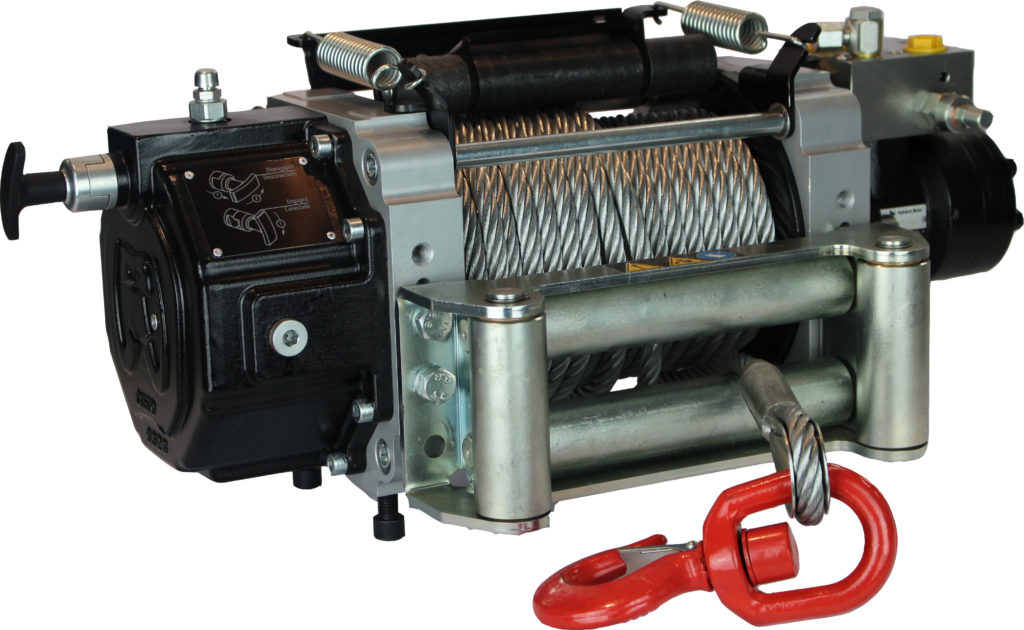
Mammoth E50 and E70 Hydraulic Recovery Winches, the evolved successors to our top-selling BZC series. These winches are equipped with a two-stage planetary geartrain, birotational functionality, and an overcenter valve for superior load control. The disc brake guarantees 100% load hold, offering reliable and secure performance.
Key enhancements include a TOP-mounted clutch for versatile mounting options, and a polyethylene cable tensioner with adjustable tension. Their robust design, featuring a painted gearbox housing and drum supports, ensures enduring durability.
IMPORTANT: Read this manual carefully and make sure you fully understand it before installing and using the winch. The following signs are used in this manual according to the type of risk the operator faces:
DANGER
Warns about dangerous situations.
If they cannot be avoided, they may cause death to the operator and the exposed people.
CAUTION
Warns about incorrect practices in the installation and use of the winch that may result in minor injuries to the operator and exposed people, and a damaged winch.
WARNING
Warns about dangerous situations. If they cannot be avoided, they may cause serious injuries to the operator and exposed people, and may also affect the winch’s operation.
NOTE
Notes give suggestions to the operator to make the use and maintenance easier, and extend the life of the winch.
If you have any doubt about its use or the correct operation, please contact our closest distributor or our after-sales service.
IMPORTANT
The operator is solely responsible for safe installation and operation.
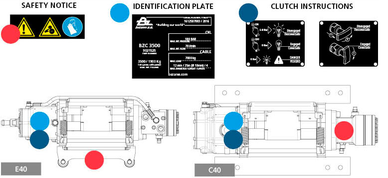
General safety recommendations
- Do not use the winch to move people, lift loads, or maintain them in certain position.
- An exposed (to the danger) person is anybody who is within the danger area, which is within a radius equal to one and a half times the length of the unrolled cable.
- Do not exceed the capabilities of the winch and the cable.
- Always wear protective gloves during regular use of the winch.
- The identification plate and the warning and use labels should always be visible.
- This instruction manual should always be included with the winch, thus, it shall always be available for consultation by the operator.
- Do not move the recovery vehicle while the cable is under tension; the force of the winch plus the force from the vehicle might overload the cable, either breaking it or causing permanent deformation.
- Do not apply sudden loads on the winch cable.
- Set the parking brake and wedge all the wheels of the recovery vehicle when using the winch.
- On platforms and tows, fasten the load with other means in addition to the winch cable.
- Do not use the winch while under the influence of alcohol, drugs, or medication.
- Do not weld or machine any of the winch parts.
- Install texts on the visible areas of the recovery vehicles, warning about the danger involved in the using the winch without having fully read and understood this instruction manual.
- Install emergency stops for the hydraulic circuit in areas accessible to the operator while using the winch, and next to potentially hazardous areas, such as the drum.
Main characteristics
Rotating direction: bidirectional.
Hydraulic motor: 63cc / 80 cc (E50 / E70)
Double overcenter valve: It regulates the load descending speed, it locks the motor in case the connection hoses break, and it releases the drum if a sudden force is applied to the cable, thus protecting the internal components of the winch.
Mechanical brake: Made of sintered bronze plates. 100% load-retaining capacity.It guarantees the load position in case of hydraulic failure, or internal leaks in the motor and overcenter valve.
Reducer system: Made up of planetary gears in two stages, total reduction 25:1.
Maximum cable rolling capacity, and maximum and minimum admissible cable diameter: For the reduced and short sizes, the diameter is 105 mm, and the thickness is 7.5 mm. The thickness is 11 mm for long cables, with a 112 mm diameter.
Clutch: Manual pull handle, manual lever or pneumatic, it releases the drum to be able to manually unroll the cable. Hydraulic clutch available upon request.
Assembly on the vehicle
These instructions should be respected in order to avoid winch misalignment under load, which might block the internal components (planetary gears, clutch, mechanical brake), cause excessive bearing wear, and breaking of fastening screws.
Use the following template for drilling in order to fasten the winch to the vehicle chassis:
The surface on which the winch is bolted should be made of steel, with a thickness no less than 10 mm, and with a flatness equal to or less than 0.4 mm..
In order to fasten the winch to this surface, eight M12 screws, of ISO 10.8 quality minimum, should be used, which should be inserted 20 to 25 mm into the aluminium winch supports.
The screws should be self-locking through impregnation, or DIN 6798-type serrated washers.
If the winch is mounted on a base plate with the holes drilled according the template indicated below, it should be screwed to the chassis with the same number of screws and of the same quality.
Drills Mounting Template
MAX PRESSURE
E50: 170 Bar
E70: 180 Bar
MAX FLOW
E50: 50 l/min. (continuous)
E70: 60 l/min. (continuous)
NOTE
Before rolling the cable and using the winch for the first time, it should be operating without a load for sufficient time so that all of the oil in the hydraulic circuit has gone through the return filter at least once. It is recommended to operate the winch without a load for 10 minutes to eliminate all the air from the circuit, and to prevent the formation of foam in the tank.
Roller guide installation (E40)
The roller guide may be assembled in three different positions, depending on where the drum will collect the cable.
The lower position of the guide is to collect the cable under the drum. Recommended.
The upper position of the guide is to collect the cable on top of the drum.
The center position of the guide is for cases where there is interference with the chassis, where the two previous assemblies are not possible. Not recommended.
The drawings show the installation for reduced, short, and long drum winches.
If the winch is not installed on the crane, be sure to perform the installation on a flat surface. Read the instructions in their entirety before proceeding with the cable gland installation.
1 Installation must be done before placing the cable on the drum. Therefore, if you already have the cable coiled, you will need to unroll it first and release the end of the fixing hole to facilitate the assembly of the springs.
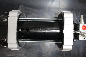
2 Remove the two upper spreader bars:
a) Loosen only the M12 Din 912 screws on one side of the guide rail.
rollers if mounted.
b) Unscrew the four Din 912 M10 screws (2) on the sides
of the winch brackets, corresponding to the upper bars.
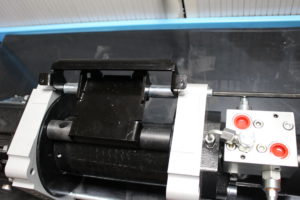
3 Install the plate and roller assembly:
a) Position the assembly (1) between the supports, in the appropriate position. It must be placed on the opposite side of the roller guide when it is mounted in the lower position. For a top mounting of the guide, the cable gland assembly will be placed on the side closest to the roller guide.
b) Secure the position using the Din 912 M10 x50 screws (2), but do not tighten them yet.
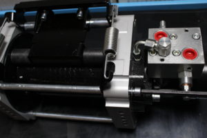
4 Fit the tensioner assembly:
a) Position the tensioners (4) (5) at the ends of the rod (3). The spring clamping area must be in an open position with respect to that of the winch supports (see figure).
b) Position the tensioner assembly between the winch brackets without moving it into position with respect to the bracket holes.
c) Insert the springs (6) (7) in the tensioning plate of the assembly, inserting the hook through the upper part of it. Make sure to place the coiled area of the spring in the position furthest from the plate.
d) Insert the other end of the springs into each of the tensioners. Make sure to place the rotated spring hook in the open position relative to the brackets (see figure).
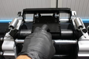
5 Position the tensioner assembly:
a) Once the springs are in place, position the tensioner assembly, using the rod (3), in the holes of the supports. Fix this position using the Din 912 M10 screws (2).
b) Tighten the four screws once they are in position.
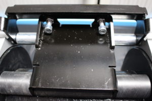
6 Adjust the tension of the cable gland (optional):
Adjust the tension of the cable gland using the screws (8) located on the center plate of the plate and roller assembly. Once the desired tension is reached, fix it using the nuts located on the screws (8). If you do not know what final tension you want, keep the screws in the supplied state (recommended).
The minimum effective breaking strength is for a new cable. Applying the UNE-EN 14492-1 regulation, the minimum cable-breaking load should double the maximum traction capacity of the winch.
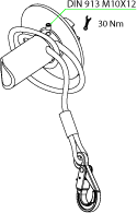
Insert the cable through the two holes, leaving two rolled turns, and screw in the DIN 913 M10x8 set screw as shown in the drawing, making sure that the cable end does not exceed the hole where the set screw is screwed.
The minimum effective breaking strength is for a new cable. Under the UNE-EN 14492-1 the minimum wire‘s breaking load must double the maximum winch traction.
Ø min Recommended 12 mm (E50) / 14mm (E70)
Minimum effective breaking load (kg) 7600 (E50) / 10400 (E70)
The maximum cable dimensions depending on the drum size are:
Ø cable 10 (35m) | 12 (25m) | 14 (20m)
E70
Ø cable 10 (45m) | 12 (30m) | 14 (25m)
(*) 25 m maximum for Ø12 and short and reinforced drums to 7000Kg.
Use a cable with the following characteristics: Galvanized 6×19+1 construction, according to standards DIN 3060 and DIN 3066 respectively, or its equivalent ISO 2408.
Minimum / Recommended resistance of the cable section: 180 Kg/mm2.
CAUTION
Wear thick leather gloves to install the cable and never let the cable run through your hands, even with the gloves on. Ensure that the clutch is in the disengaged position and that the drum can be rotated manually.
NOTE: Completely unroll the cable on the floor, making sure that it does not fold on itself; this will facilitate rolling the cable on the drum.
WARNING
When rolling the cable for the first time, apply a minimum load of 50 kg to the cable to prevent trapping of the external turns on the internal ones, which would cause deformation and knots in the cable when working with a heavy load. Roll the cable in an ordered way.
CAUTION
If the cable was already rolled at the factory,
it must be rolled again in the previous conditions.
DANGER
The set screw does not retain the cable under load by itself. Leave at least 5 turns of rolled cable on the drum to operate safely.
NOTE: It is recommended to paint the last two meters of cable in red or yellow, on the opposite end to the hook; this will warn you that the cable is on the last layer and that there are approximately 8 rounds left, 3 to reach the hazardous area.
The drum has been designed so that the cable does not completely unrolled due to the operator error, leaving two rolled turns. These two remaining turns may prevent the cable from coming free under load, but they do not resist the maximum force that the winch is designed for. If overlooked, the cable would be rolled in the opposite direction, and it might be seriously damaged.
Follow the hydraulic connection instructions on the overcenter valve, shown in the following figure, in order to obtain the desired rotating direction based on where the drum will collect the cable.
Pneumatic clutch installation
The pneumatic version of the clutch consists of a simple effect pneumatic cylinder. The air pressure for actuation should be between 6 and 8 bar. The body has a machined 1/8 BSP thread and the supplied quick connector is for 6×4 tube.
At the back part there is the piston vent and a switch (opened) that closes the circuit when the clutch shaft is not at its rest position, that is, it has not entered completely or that the pneumatic valve is at the disengaged position.
This switch should be used to close a circuit supplying a visual or acoustic signal; it can also be combined with the remote command to cancel the lifting function until the clutch is completely engaged.
Dark blue = Continuous
Light blue = Intermitent
Practice
The best way to prevent accidents and extend the life of all the winch components is to practice before using it. There are two parameters the operator can easily control while handling the winch: the collecting speed and the sound of the winch and the valves.
Get used to differentiating the cable speed depending on the layers rolled on the drum. The internal layers collect the cable at a slower speed. The cable speed should be practically the same working with or without load.
Get used to the sound of the winch itself (planetary gears) and of the hydraulic block (hydraulic distributor and pressure relief valve in the circuit).
Differentiate between working without a load and with light load, a very heavy load and a load exceeding the winch dragging capacity, which causes the cable to stop, even if the hydraulic distributor is activated. Use a pulley in this last case.
Free drum rotation
WARNING
Never perform this operation with the cable loaded.
This operation is necessary when the cable has to be manually and quickly unrolled without starting up the hydraulic circuit, as well as for maintenance tasks and installation of accessories.
DANGER
Leave at least 5 turns rolled on the drum to operate safely.
Manual Clutch
In the engaged position, turn the lever 180º counterclockwise.
You will notice how the lever ascends as it rotates, releasing the internal mechanism.
In disengaged position, you can freely rotate the drum, although with some resistance.
The unwinding of the cable should be easy to do, pulling the hook with your hands.
To re-engage, turn the lever 180º clockwise
You have two options if the handle/lever does not return to its position:
– Pull the cable to rotate the drum.
– Activate the winch to reel in the cable, while fastening the cable at the same time; the drum will not rotate until the clutch does not return to its position.
Pneumatic clutch
Activate the pneumatic valve that commands the clutch; the acoustic / illuminated alarm described in section 2.7 will emit a signal.
Unrolling the cable may be done easily by manually pulling the hook. In order to re-engage the clutch, locate the pneumatic valve in the engaged position; the acoustic alarm will stop its signal when the shaft is in the engaged position. If it does not return to this position, you may use the method described previously in the manual clutch section. the manual clutch section.
Reeling in the cable
DANGER
Never perform this operation if there are less than five turns of rolled cable on the drum.
WARNING
Do not roll the cable when it is loaded if the clutch is not fully engaged.
Activate the hydraulic distributor to the cable reel-in position.
Before moving the load, gently tighten the cable with slow and short movements in order to prevent sudden pulls that may exceed the maximum force of the winch for an instant in time.
Remember that the force needed to start moving a load is greater than to keep it moving.
Avoid short movements with constant stops with the cable under load.
If the load to be moved is very heavy, use the last layer to start moving it; this will generate more force, and prevent the upper layers from getting into the lower ones, ending up deformed (knots).
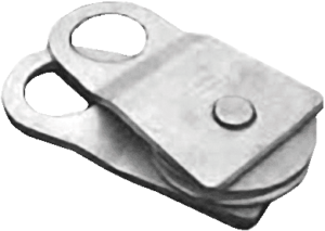
If the drum stops because the load exceeds the force developed by the winch, use a pulley (on the load) and connect the hook on a part of the chassis that is separate from the one used to assemble the winch.
Using a pulley doubles the pull force.
Avoid lateral pulling angles greater than 20º; use a pulley in these cases. If the length of the unrolled cable is more than 10 m, place a blanket, jacket, or something similar at approximately 2 m from the hook; this will partly prevent the cable from whipping in case of being released from the hook.
WARNING
Uneven rolling of the cable on the drum is not a big problem. Avoid rolling at one side of the drum; it might cause serious damage to the cable and the winch, which may ruin both of them.
In this case you should:
- Fasten the load, with the cable being under load.
- Release a little bit of cable.
- Check that the load does not move and release the hook. Unroll all the cable that was rolled unevenly on the drum.
- Roll it again in an orderly manner, following the instructions previously described for the cable installation.
Never try to guide the cable onto the drum with your hands when it is under tension.
Check the planetary gear housing temperature. You should be able to bear the temperature when touching the housing with your hand; if not, let it cool.
In order to stop the winch, place the hydraulic distributor in its center rest position.
Unrolling the cable under load
DANGER
Do not release the hook from the load until securing the load, and verifying that the cable is not under tension.
In order to unroll the cable under load, place the hydraulic distributor to the unrolling position. The overcenter valve controls the load descending speed. A slow and even descent is recommended instead of a fast one with constant stops; the load inertia may cause impact forces that are higher than the retaining forces developed by the winch.
WARNING
Perform all the maintenance operations with the winch stopped, without pressure in the hydraulic circuit and without tension on the cable.
Regular maintenance of the winch
Annual
Check the braking capability of the mechanical brake:
- Unscrew the end of the fitting over the overcenter valve.
Be careful with the closing washer that seals the tube against the valve. - Unscrew the bolts that fasten the hydraulic motor to the motor support.
- Remove the motor-overcenter valve assembly without moving the pilot fitting.
- Adjust the device Code 9030499 on the winch shaft, and apply a torque of 250 Nm; the shaft should not rotate. Otherwise, contact our after-sales service.
Change the oil lubricating the gears and the brake:
Capacity E50: 0,9 liters
Capacity E70: 1,3 liters
Use oil to lubricate the gear reducers with EP additives and a viscosity index higher than 95, according to standard ISO 6743-6 CKC or DIN 51517 CLP. The viscosity grade will be chosen depending on the room temperature, according to the following table:
| wdt_ID | OIL Type | ISO VG 100 | ISO VG 150 | ISO VG 320 |
|---|---|---|---|---|
| 1 | MAX room temp (ºC) | 5º | 30º | 60º |
| 3 | MIN room temp (ºC) | -20º | 5º | 30º |
CAUTION
It is very important to follow all the steps in the following order.
- Unscrew the upper and lower plugs of the gear housing to empty the oil.
- Let all the oil drain completely.
- Screw in the lower plug again.
- Unscrew one of the lateral plugs to check the oil level when filling through the upper plug.
- Screw in the lateral plug and lastly the upper one.
The plugs should be tightened to a torque of 30 Nm.
Monthly
Lubricate the manual clutch with oil. Engage and disengage it several times to complete the lubrication. Check that all the winch screws are tightened, including the ones fastening it to the chassis. Check the level of oil by unscrewing one of the lateral screws on the gear housing. If necessary, refill; follow the previous instructions.
Daily
Check that there are no oil leaks. Cable lubrication is very important. When the cable operates, the internal wires move and rub against each other; the external wires wear out by rubbing against the pulleys and drums.
The lubricant reduces the wear, internally and externally; it also protects against corrosion. Lubricate the cable following the manufacturer’s instructions (very viscous oil or very light grease with adhesive additives, such as molybdenum bisulfate is recommended) and check that it has been perfectly rolled, as indicated in section 2.6. Clean the outside of the winch. Do not use a water jet; it might damage the seals and watertight o-rings.
After each use
Verify the condition of the cable (see section 4.2) and the hook.
Roll the cable as indicated in section 2.6.
Cable inspection
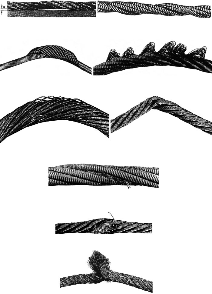
Examples of permanent deformations for which the cable must be replaced.
Troubleshooting
| wdt_ID | PROBLEM | ROOT CAUSE | SOLUTION |
|---|---|---|---|
| 1 | The drum does not rotate without load. | 1. Faulty break. 2. Lack of brake pilot pressure. 3. Assembly on chassis defective. Poor alignment of the lateral winch supports. 4. Blocked or defective reducing planetary gears. 5. Clutch in disengaged position. | 1. Replace brake 2. Replace overcenter valve. 3. Verify the assembly (flatness, dimensions between holes, etc.) on the vehicle, as shown in section 2.2 4. Clean or replace the affected gears. 5. Make sure the clutch is in the engaged posit |
| 2 | The drum does not rotate with load, but it does without one. | 1. Higher load than the one allowed by the winch. 2. Insufficient pressure in the hydraulic circuit. 3. Defective motor. | 1. Verify that you are not exceeding the winch pulling specifications (section 3.1). 2. Use a pulley as indicated in section 3.3 Verify that the hydraulic circuit meets the specifications in section 2.3. 3. Replace the motor. |
| 3 | The winch rotates slowly. | 1. Insufficient pump flow 2. Worn hydraulic motor. | 1. Verify that the hydraulic circuit meets the specifications in section 2.3. Verify that the tank oil level is correct. Verify that the pump is operating correctly. 2. Replace the hydraulic motor. |
| 4 | The cable cannot be unrolled freely with the clutch in the disengaged position. | 1. Defective clutch assembly. 2. Assembly on chassis defective.Poor alignment of the lateral winch supports 3. Blocked reducing planetary gears 4. Blocking or knotting in the rolled cable. | 1. Disassemble the clutch assembly and verify that the rod does not project out in its movement more than 11 mm. 2. Verify the assembly (flatness, dimensions between holes, etc.) on the vehicle, as shown in section 2.2. 3. Clean or replace the aff |
| 5 | Oil leakage through the oil filler cap’s evaporator (steel). | Defective brake. | Replace the brake. |
| 6 | Oil leakage through the oil filler cap’s evaporator (steel). | Defective drum seals. | Replace the drum seals. |
| 7 | The load does not maintain its position. | 1. Defective brake. 2. Overcenter defective or with internal dirt. | 1. Replace the brake. 2. Clean the cartridges and selector or replace the overcenter completely |
| 8 | Excessive noise. | 1. Assembly on chassis defective. Poor alignment of the lateral winch supports 2. Excessive rotating speed 3. Very low oil level in the tank. | 1. Verify the assembly (flatness, dimensions between holes, etc.) on the vehicle, as shown in section 2.2. 2. Verify that the hydraulic circuit meets the specifications in section 2.3 3. Fill the tank to the appropriate level. Purge the air circui |
| 9 | Vibration and excessive noise when rotating without load. | Overcenter defective or with internal dirt. | Install a pressure gauge at the pressure inlet on the overcenter valve (according to the activated function, up or down) and tighten the cartridge adjustment screw located on the return side of said valve until the pressure gauge reads between 44 and 48 b |
CE Certificate of conformity
The company Bezares S.A. located at Avenida de las Retamas, 145, Polígono Industrial Monte Boyal, Casarrubios del Monte, Toledo, España C.P: 45950, declares under it’s sole responsability that the machine:
Meets all the requirements of the Directive 2006/42/CE (DOUE L-157. 09-06-2006) on machinery.
Authorised person, stablished in the community, to make the technical documentation:
Alberto López Torrecilla. Bezares S.A.
For the record and the relevant purposes Emilio Nunez certifies this as head representative of Bezares SA Casarrubios del Monte, Toledo, Spain, dated January 1, 2010.
Bezares S.A.
+34 918 188 297 • [email protected] • bezares.com
Avenida de las Retamas 145, Polígono Industrial Monte Boyal, Casarrubios del Monte, 45950, Toledo, España
Warranty information
All of our products are guaranteed against all manufacturing faults. The guarantee for use will be understood as for one year commencing from the date of the dispatch of the goods, with the reservation that the guarantee will depend on the treatment that the goods had received and will only be valid with a necessary report from our Technical Service Department.
The manufacturer will not be liable to pay any compensation for loss of profits or losses brought about by product defects beyond that stated in this same point in regard to the guarantee.
Returnings
In order to make any return of goods we must be advised in advance. Our warehouses will not accept any despatch of returned goods that are sent “Carriage Due” and/or not authorised by BEZARES, S.A. Returns will not be accepted after 30 days from the date of the delivery note.
- All returned materials will be inspected by the materials reception department to decide on their state.
- The material must be completely new, without having been used and that is currently on sale, this being that it is not obsolete.
- It is absolutely necessary that any return is previously informed, and authorized by Bezares’s After-sales Department. Each package has to include inside, complete documentation explaining the reasons of the return, and the sticker outside, showing us “RETURN”. The forms and the stickers are included inside the packing of all Bezares products.
- Consult refunds policies with our customer service department.
Liability
Bezares, S.A. will not be held liable under any circumstances for their use or the defective assembly of its products, for breakdowns caused by external agents, excessive loads, inadequate lubrication, defects that may appear in the fitting of gear boxes to used vehicles, or for any other cause or accident outside of its control.

