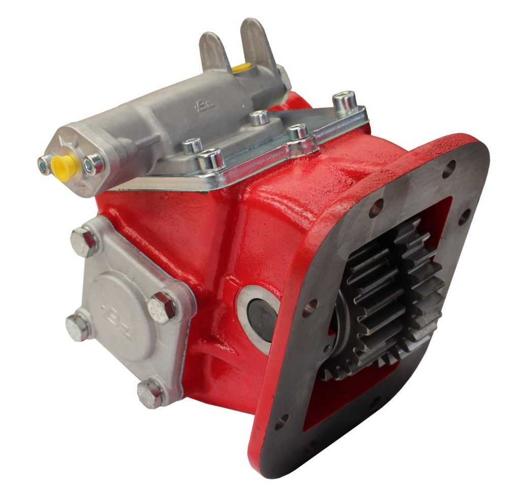
Compatible with the most common transmissions in the market. The 8500 / 8510 series PTOs feature a wide range of input gear, ratio, output, and shifter options. All cast iron construction with large 12mm flange bolts to support some of the larger pumps in the market.
Features and benefits:
- Industry exclusive idler shaft with locking nut and snap ring.
- Deep gear tooth carburization for longer gear life.
- Larger flange mounting hardware provides additional support and reduces failures caused by heavy pumps – best in class.
- Industry leading Garlock gasket material provides better tear resistance and easier installation, with Viton o-ring material & shaft seals to prevent leaks.
- Symmetrical design allows for multiple configuration options and ease of installation.
- Simple and robust mechanical air shift operation.
- Quiet operational noise levels for an improved operator experience.
Competitive with:
Typical Applications: Dump Trucks and Trailers, Walking Floor, Low Boy, Vacuum Pumps, and more…..
CAUTION
TO PREVENT POSSIBLE INJURY:
- DO NOT go underneath the vehicle with the engine running.
- DO NOT attempt to work on an installed Power Take-Off with the engine running.
- DO NOT operate the controls of the Power Take-Off or other driven equipment from underneath the vehicle with the engine running.
- DO NOT operate the controls of the Power Take-Off or other driven equipment in any position that could result in getting caught in the moving machinery.
Make sure to block any moving or raised device that may injure a person working on or under the truck. A lever or its linkage may be accidentally moved causing movement of the device which could cause injury to a person near the device.
IMPORTANT
Because most of our Bezares Power Take–Offs and P.T.O. drive lines are sold through distributors, the product applications and the resulting degree of exposure to danger of the operators are beyond the knowledge and controls of BEZARES.
Therefore, the proper installation of the P.T.O. and its associated equipment, and the decisions of whether to install guards and/or warning signs shall be the responsibility of the designers or installers.
Since it is our major objective to show you how to get additional and more profitable miles from truck, tractor and trailer components, we want to provide you with information on the installation of 4100, and 4250 Series.
We all realize that an inadequate transmission will overwork any Power Take–Off in a very short period of time. In addition, a mismatched transmission/P.T.O. combination can result in unsatisfactory performance of the equipment right from the start.
Before you order new trucks be sure that you’re getting the right transmission/P.T.O. combination. It is of vital importance for efficient performance to have adequate power.
To help you select the proper type, size and design of P.T.O. it is advisable to discuss your specific requirements with a Bezares P.T.O. specialist. They know their products and Power Take–Offs. They can inform you about everything you need to know about power, at the right time, before you specify components.
Here are some of the questions that are relevant to the Proper Selections of a Transmission mounted Power Take–Offs.
- What is the make and model of your transmission?
- Which P.T.O. opening will be used?
- What accessory is to be driven?
- How much horsepower is required to drive the accessory?
- What is the required rotation of the P.T.O.?
- What is the required P.T.O. output shaft speed as a percent of engine speed?.
- What is the required method of shifting the P.T.O., mechanical or pneumatic?
Once all of the answer to these questions have been determined, a transmission mounted P.T.O. can be selected to meet the horsepower, speed and rotation that you require.
Check out our PTO Selection form at bezares.com/pto-selection-tool/
Having made the selection of a P.T.O., you are ready to start the installation.
General Information
The following instalation instruction for fitment of the PTO’s 8500 & 8510 series should be followed in order to ensure good performancce and long life.
Where it is obvious that this instructions have not been followed, then warranty claims will not be accepted.
Mounting Instruction List
1 – Gasket (2x)
2 – Spacer
3 – PTO housing
4 – Bolt M8x16 (2x)
5 – Bolt M10x25 (4x)
6 – Steel Cover
7 – Stud (8x)
8 – Nut (8x)
9 – Washer (8x)
10 – Gasket
Installation Method
Drain the gearbox and clean the cover plate and surrounding area to prevent ingress of dirt.
Remove the PTO cover and clean the sealing surface.
Mount the studs (7) included in the mounting kit, in accordance with the pattern shown.
Fit the gasket (1) plus a spacer (2) and plus another gasket (1) on the gearbox and mount the PTO housing (3).
Mount four of the nuts (8) with the washers (9) in each corner of the PTO mounting flange and fit it to the gearbox applying pressure on it.
The backlash shall be 0,15-0,30 mm (0,006-0,012”).
If the backlash is too large, remove the PTO and select a thinner gasket.
If the backalsh is too small, select a thicker gasket or add a second gasket
Fit the PTO with nuts (8) and washers (9) in accordance the pattern shown.
Thread again the 4 bolts (5) and 2 bolts (4) using loctite 270 or similar and using a new gasket furnished in the mounting kit (in case it was damaged). Thightening to the torque shown.
Fit a gasket (10) between pump and PTO housing.
For mount the switch, first remove the plug and thread the switch with its washers, tighten the switch in accordance with the torque shown in the drawing.
Do not forget to refill the gearbox with suitable oil and up to level.
Drive the vehicle a short distance, park the vehicle and shut down, then verify.
CAUTION
This vehicle is equipped with a Power Take-off.
Shut engine off before working on Power Take-Off or getting below vehicle.
Consult operating instructions before using.
POWER TAKE-OFF OPERATION VEHICLE STATIONARY.
- Mechanical Transmission.
A power take-off is, and should be, operated as an integral part of the main transmission.
Before shifting the power take-off into or our of gear, disengage the clutch and wait for transmission or P.T.O. gears to stop rotating. - Automatic transmission with manual shift P.T.O. (Includes air shift).
On automatic transmissions, the gears in the transmission turn when the transmission is in neutral, therefore, gear clashing will ocurr if the power take-off is shifted into gear at this time.
With converter driven gear:
• Shift transmission lever into any of drive positions. (This will stop the transmission gear from turning).
• Shift power take-off into gear.
Shift transmission into neutral. (This will start transmission gears turning.)
• Shift P.T.O. into gear before starting engine.
This procedure should eliminate gear clash.
IMPORTANT
Failures to follow proper shifting or operating sequences will result in premature P.T.O. failure with possible damage to other equipment.
Warning: Follow all local, state and federal safety precautions. Also adhere to all company safety procedures before, during and after PTO installation.
Caution: Protect wiring for more severe environmental and corrosive conditions.
It is recommended the installer ensures all wired connections are sealed to help prevent moister intrusion and reduce possibility of corrosion. Following this recommendation may ensure better performance in severe environmental and/or corrosive conditions.
Note: Read the truck manufacture operation’s manual before starting the install.
Reference Eaton: TRIG2600 July 2019 installation Guide for wiring and connection information when installing the Bezares PTOs
Note: Read the truck up fitter document for your particular truck model and manufacturer before starting.
PACCAR INSTALLATION REQUIREMENTS
1. Sales order code KENWORTH: Option code 8205164 – SINGLE ACTING PTO SWITCH
2. When selecting and purchasing the new truck with an (PACCAR) Eaton Endurant transmission, ensure the factory installs the PTO Prep Kit.
3. Ensure the transmission control module (TCM) has the J1939 feature enabled.
4. The PACCAR PTO harness # P92-5075-2000 must also be ordered for the installation.
5. Verify the transmission air tank is charged with appropriate pressure.
ADDITIONAL PETERBILT REFERENCE ONLY CODES
Option 4233900-(1) DASH SWITCH MTD SINGLE ACTING EOA PTO CONTROL ELECTRIC OVER AIR
Option 2140460-REMOTE PTO/THROTTLE, 12PIN 250K, BOC/BOS, J1939, REMOTE CONTROLS PROVISION-For control of the engine RPM outside the cab
Option 2140510-REMOTE PRESETS 7 INTERLOCK, 8-PIN, BOC/BOS: requires 2140460 or 2140480. Offers ability to drive engine to a second rpm that is always active when the PTO is engaged with a switch outside the cab
NAVISTAR INSTALLATION REQUIREMENTS
1. Ensure the transmission control module (TCM) has the J1939 enabled
2. Have the dealer order the listed below codes for the correct PTO prep package
Order Sales code: 13WEW-wiring harness PTO
Order Sales code: 13XAA- switch/air manifold
Order Sales code: 13XAR- location-8 bolt bottom
General Information
The following instalation instruction for fitment of the PTO’s 8500 & 8510 series should be followed in order to ensure good performancce and long life.
Where it is obvious that this instructions have not been followed, then warranty claims will not be accepted.
Mounting Instruction List
1 – Gasket
2 – PTO housing
3 – Bolt M10x25 (4x)
4 – Steel Cover
5 – Bolt M8x16 (2x)
6 – Gasket
7 – Passing contact switch
8 – Stud (8x)
9 – Washer (8x)
10 – Nut (8x)
Installation Method
Drain the gearbox and clean the cover plate and surrounding area to prevent ingress of dirt.
Remove the PTO cover and clean the sealing surface.
Fit the studs (8) included in the mounting kit, in accordance with the pattern shown.
Fit the gasket (1) on the gearbox and mount the PTO housing (2).
Mount four of the nuts (10) with the washers (9) in each corner of the PTO mounting flange and fit it to the gearbox applying pressure on it.
The backlash shall be 0,15-0,30 mm (0,006-0,012”).
Fit the PTO with nuts (10) and washers (9) tighten the nuts in accordance the figure shown.
Thread again the 4 bolts (3) and 2 bolts (5) using loctite 270 or similar and using a new gasket furnished in the mounting kit (in case it was damaged). Thightening to the torque shown in the figure.
Fit a gasket (6) between pump and PTO housing.
For mount the switch (7), first remove the plug and thread the switch, tighten the switch in accordance with the torque shown in the drawing.
Do not forget to refill the gearbox with suitable oil and up to level.
Drive the vehicle a short distance, park the vehicle and shut down, then verify.
General Information
The following instalation instruction for fitment of the PTO’s 8500 & 8510 series should be followed in order to ensure good performancce and long life.
Where it is obvious that this instructions have not been followed, then warranty claims will not be accepted.
Mounting Instruction List
1 – Gasket (2x)
2 – Spacer
3 – PTO housing
4 – Bolt M8x16 (2x)
5 – Bolt M10x25 (4x)
6 – Steel Cover
7 – Gasket
8 – Stud (8x)
9 – Washer (8x)
10 – Nut (8x)
11 – Passing contact switch
Installation Method
Drain the gearbox and clean the cover plate and surrounding area to prevent ingress of dirt.
Remove the PTO cover and clean the sealing surface.
Mount the studs (7) included in the mounting kit, in accordance with the pattern shown.
Fit the gasket (1) plus a spacer (2) and plus another gasket (1) on the gearbox and mount the PTO housing (3).
Mount four of the nuts (8) with the washers (9) in each corner of the PTO mounting flange and fit it to the gearbox applying pressure on it.
The backlash shall be 0,15-0,30 mm (0,006-0,012”).
If the backlash is too large, remove the PTO and select a thinner gasket.
If the backalsh is too small, select a thicker gasket or add a second gasket
Fit the PTO with nuts (8) and waskets (9) in accordance the pattern shown.
Thread again the 4 bolts (5) and 2 bolts (4) using loctite 270 or similar and using a new gasket furnished in the mounting kit (in case it was damaged). Thightening to the torque shown.
Fit a gasket (10) between pump and PTO housing.
For mount the switch, first remove the plug and thread the switch with its washers, tighten the switch in accordance with the torque shown in the drawing.
Do not forget to refill the gearbox with suitable oil and up to level.
Drive the vehicle a short distance, park the vehicle and shut down, then verify.
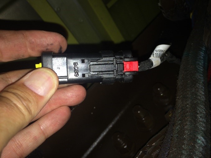
1. Locate the TCM connector, it is on driver side frame rail near top of transmission.
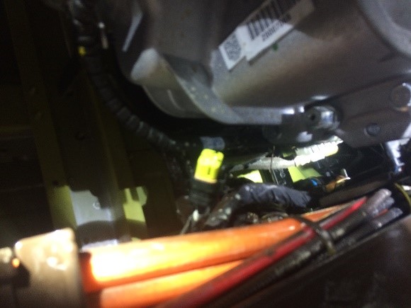
2. Remove end cover from sealed connector to expose pins.

3. Connect wire harness, P92-5075-2000, to connector.
ELECTRIC ENGAGED EQUIPMENT
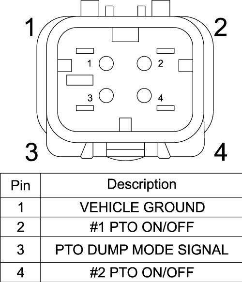
At the left hand forward cab mount, P198 is available for PTO controls that are electrically engaged via ground.
– PTO PIN 2 completes the ground loop feedback and is part of PACCAR harness P92-5075-2000 which has two sections.
– This 4 Pin connector is terminated with second section wire connector with Metripak 280 single pin shown in picture 3 below
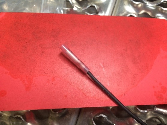
4. Cut off the single wire end and strip insulation off approx. ¾ inch. Length is determined at assembly.

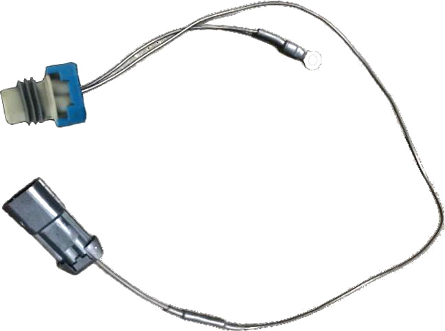
5. Modify the indicator ball switch connector wires same way, both leads, length is determined at assembly.
a. Using a butt splice, connect the bare BZ indicator ball switch wire to bare wire harness lead, cover with heat shrink.
b. Strip the other BZ wire end the affix it to appropriate electrical system ground. Battery negative (-) terminal is recommended.
6. Ensure all lose wires are secured from hot and rotating parts.
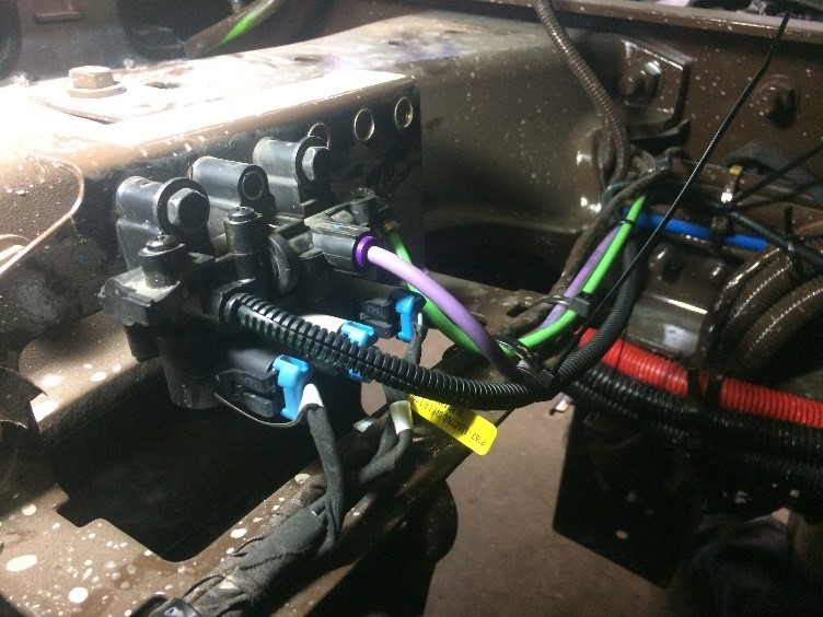
1. Locate air solenoid valve on truck frame cross member behind the cab.
2. Remove the dust cover from the solenoid air outlet port.
3. Use the appropriately rated ¼ inch airline and insert into valve output port
4. Route the ¼ inch airline to the PTO in such a way to keep from contacting or coming near hot and rotating parts.
5. Cut airline to require length and push on the air shift BSP shifting inlet port.
6. Secure the airline appropriately.
1. There are two feed-back wire color combinations based on engine selection. If the LT tractor has the X15 Cummins, colors are green and purple. Purple is PTO # 1. If the LT tractor has the A26 engine there are two green wires. They are marked K88 and K88A. K88 is for PTO # 1 is also known as PTO A -8 bolt bottom
2. Connect one of the indicator switch leads to either X15 (purple) or A26 (green wire K88).The other lead goes to battery ground. That completes the feedback loop required for PTO # 1 operation
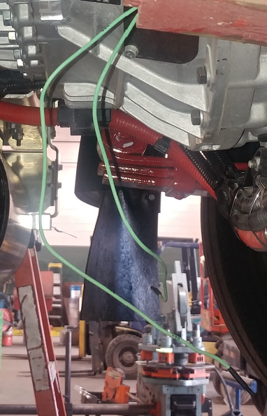
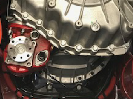
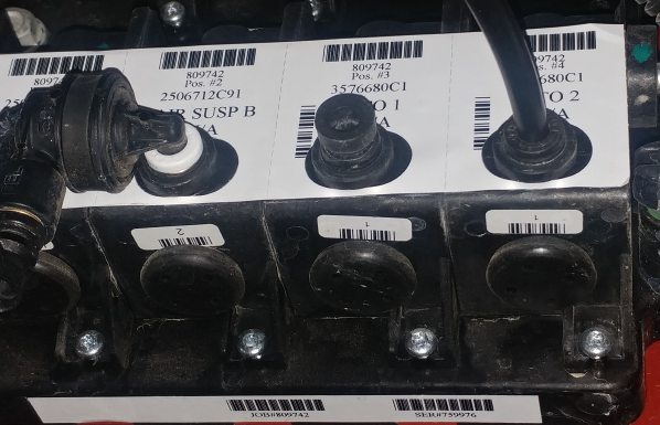
1. Locate the air solenoid manifold valve located on passenger side inner frame rail. There are two ¼ inch push in solenoids marked PTO # 1 and PTO # 2. Plug the airline from 8 bolt PTO into solenoid marked PTO # 1
2. PTO # 1 is also PTO A. NOTE! PTO, # 2 is also PTO B. PTO B is for rear countershaft only
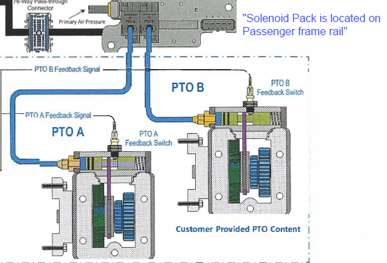
3. Insert ¼ inch airline into air manifold marked PTO # 1. Cut airline to fit and insert in ¼ inch air bung on PTO # 1 or PTO A
1. Read and follow the truck’s manual before attempting to run PTO
2. Verify tranny has adequate fluid and extra fluid to compensate for PTO (DO NOT OVER FILL)
3. Follow all company, federal, state and local safety procedures and guidelines.
4. Apply parking brake.
5. Truck must be in neutral.
6. Insert key in ignition.
7. Verify no one is under vehicle or near any rotating parts – ALL CLEAR!
8. Start engine, the PTO is not engaged and the output shaft is not turning.
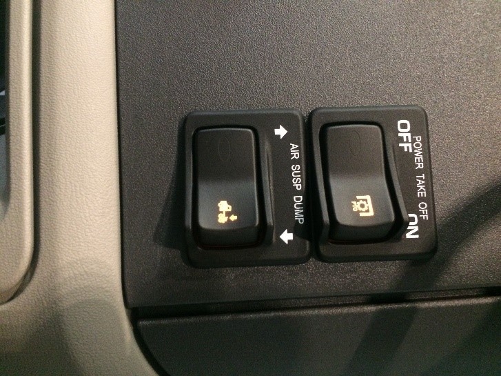
9. Start engine, the PTO is not engaged and the output shaft is not turning.
10. The PTO now shifts, and the output shaft is rotating. There may be some audible gear noise, this is normal and does not diminish the form, fit of function.
11. Depress the PTO rocker switch to disengage PTO and discontinue output shaft rotation.
1. Check for leaks, fix any if found.
2. After truck warms up check all hardware for proper torque, tighten as needed.
3. Check all wire connections, ensure they are correctly installed and away from heat and rotating parts, fix and repair as needed.
4. Check the airline, ensure it is correctly installed and away from heat and rotating parts, fix and repair as needed.
Proper maintenance of your Power Takeoff (PTO) is crucial to ensure the longevity and optimal performance of your vehicle. Follow these tips to maintain your PTO:
Safety First: Do not go under or near PTO when the engine is running. Shut off the engine and disconnect batteries on electric motor-driven PTOs (i.e., hybrid vehicles) before checking or servicing.
Service Intervals: The PTO, being an integral part of the transmission, should be serviced at the same intervals as the transmission. Transmission fluid changes should follow the interval recommended by the vehicle manufacturer for severe service.
Check for Leaks: Checking for PTO leaks and checking the transmission oil level should be done regularly. Loss of oil can significantly affect or damage the transmission. Check for leaks upon delivery of the vehicle and after initial operation of equipment.
Maintenance Checks: The PTO requires periodic checks. Typically, the interval for maintenance checks of the PTO depends on the application of the vehicle. For severe-duty PTO applications, it is recommended that the PTO be checked for service every 100 hours of use (this guideline can be adjust-ed based on past service history once you have it established). Service should include checking and lubricating direct-mount pump shaft connections on a regular basis.
Recheck the Installation: Within the first week of use, recheck the installation of the PTO. Check for leaks in air lines or hydraulic connections with air shift or hot shift PTO’s and loose mounting hardware (studs, cap screws, nuts). Recheck the cables or lever connections for proper adjustments and lubricate moving parts, tighten and repair ALL connections, hoses, mounting hardware, cable, and lever connections.
Visual Inspection: It is recommended that the operator/owner do a visual inspection for leaks under and around the vehicle and equipment before entering or starting the equipment on at least a weekly basis. Any leaks should be corrected immediately.
Anti-Seize or High-Temperature Grease: Pumps that are directly mounted to the PTO output require the application of anti-seize or a high-temperature, high-pressure grease (unless the PTO is a wet spline option). The purpose of this grease is to help make the PTO easier to service and to reduce the effects of fretting corrosion on the mating PTO and pump shafts. PTO’s under severe duty cycles and/or high torque requirements may require servicing of this pump shaft connection by periodically regreasing the shafts. Vehicles with low-speed engines are also considered severe duty applications due to the inherent vibrations of the vehicles. Fretting corrosion cannot be stopped by greasing the shafts; it is only a deterrent. Wet spline PTO’s do not require servicing this connection.
Remember, failure to comply entirely with the provisions set forth in the appropriate Owner’s Manual will result in voiding of ALL Warranty consideration.
For any queries, contact your equipment installer.
PTO Troubleshooting
| wdt_ID | PROBLEM | REASON | CORRECTIVE ACTION | PREVENTION |
|---|---|---|---|---|
| 1 | PTO is Noisy (whines) | -insufficient mounting backlash | -remount PTO adding gaskets to achieve backlash of .006-.012” | -check and set proper backlash |
| 2 | PTO is Noisy (rattles) | -excessive mounting backlash | -remount PTO removing gaskets to achieve backlash of .006-.012” | -check and set proper backlash |
| 3 | PTO is Noisy (clicks) | -damaged/worn gear tooth | -replace damaged/worn gear | -check and set proper backlash |
| 4 | -overloading PTO | -reduce load | -review application | |
| 5 | Leaking Shaft Seal | -dirt under seal | -replace seal | -preventive maintenance |
| 6 | -damaged seal or cover | -replace seal or cover | -preventive maintenance | |
| 7 | -improperly seated seal | -replace seal | -preventive maintenance | |
| 8 | -worn shaft at seal area | -replace output shaft/seal | -preventive maintenance | |
| 9 | Leaking Output Flange | -torn flange gasket | -replace gasket | -preventive maintenance |
| 10 | -loose flange bolts | -properly torque flange bolts | -preventive maintenance | |
| 11 | -direct mount pump improperly supported | -install pump support brackets | -review application requirements | |
| 12 | Leaking Mounting Face | -torn mounting gasket | -replace mounting gasket | -preventative maintenance |
| 13 | -cracked mounting pad | -replace housing/set backlash | -proper mounting torque | |
| 14 | -broken mounting shim | -replace mounting shim/set backlash | -preventative maintenance | |
| 15 | -improper gaskets/shim used | -replace gaskets/shim | -ensure proper gaskets/shim are used | |
| 16 | Leaking Bearing/Shift | -torn gasket | -replace gasket | -preventive maintenance |
| 17 | COVER | -loose cap screws | -properly torque cap screws | -preventive maintenance |
| 18 | Cracked Housing | -insufficient backlash | -replace housing/set backlash | -check and set proper backlash |
| 19 | -unsupported direct mount pump | -replace housing/attach pump support bracket | -review application | |
| 20 | -over torque condition | -replace housing | -review application | |
| 21 | -foreign object between gears | -replace housing/gears | -preventive maintenance | |
| 22 | -impact with external object | -replace housing | -install protection/avoid impacts | |
| 23 | -shock load/cold relief pressure | -replace housing | -allow oil to warm before loading | |
| 24 | PTO Failure | -broken/damaged parts | -inspect/replace damaged parts | -preventive maintenance |
| 25 | -driveshaft problem | -check phasing, angle, and slip of driveshaft | -preventive maintenance | |
| 26 | -worn/damaged driveshaft components | -repair/replace driveshaft | -preventive maintenance | |
| 27 | PTO Does Not Engage/ Disengage (wire shift) | -worn/damaged shift control | -repair/replace components | -preventive maintenance |
| 28 | -loose/missing linkage/attachments | -adjust/replace components | -preventive maintenance | |
| 29 | -worn/damaged cable | -repair/replace components | -preventive maintenance | |
| 30 | PTO Does Not Engage/ Disengage (air shift) | -lack of air pressure | -ensure pressure exceeds 100psi/governor cut-in | -preventive maintenance |
| 31 | -shifter damaged | -replace shifter | -install protection/avoid impacts | |
| 32 | -shifter piston leaking | -replace shifter seals | -preventive maintenance | |
| 33 | -shifter piston does not move | -check for contaminates in air cylinder | -preventive maintenance | |
| 34 | -contaminated air lines | -clean air systems | -preventive maintenance | |
| 35 | -worn/damaged shift control | -repair/replace components | -preventive maintenance | |
| 36 | PTO Does Not Engage/ Disengage (all) | -shift fork not in shift collar | -check/reinstall shift cover | -preventive maintenance |
| 37 | -internal gears do not mesh | -check for internal debris/damage | -preventive maintenance | |
| 38 | -improper shifting | -adjust vehicle clutch | -review transmission manual |
