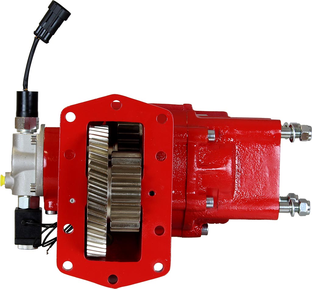
Engineered for heavy-duty performance, these series offer an extensive range of input gears, ratios, outputs to fit various needs. Built with reinforced cast iron, they are designed to support even larger and more demanding pumps in the market.
Features and benefits:
- Reinforced flange mounting hardware, larger than standard, provides exceptional support and significantly reduces failure risks with heavy-duty pumps – setting a new industry standard.
- Advanced Garlock gasket material for superior tear resistance and straightforward installation, complemented by Viton o-ring materials and shaft seals for leak prevention.
- Optimized design for reduced operational noise, ensuring a better operator environment.
- Internally lubricated for ease of installation, improved bearing life and cooler operation.
- Clutch pack material is designed to provide smooth engagement and long life.
- Higher torque rating than competitors within the same PTO segment.
- All hoses, hardware, and wiring are included.
Ideal for:
- Heavy-duty Trucks and Trailers,
- Construction Equipment,
- High-Capacity Vacuum Pumps,
- Industrial Applications, and more…
Competitive with:
- Muncie CS24
- Muncie CS41
- Chelsea 870
- Muncie CS10 “Better profile”
- Chelsea 859
- Chelsea 280
CAUTION
TO PREVENT POSSIBLE INJURY:
- DO NOT go underneath the vehicle with the engine running.
- DO NOT attempt to work on an installed Power Take-Off with the engine running.
- DO NOT operate the controls of the Power Take-Off or other driven equipment from underneath the vehicle with the engine running.
- DO NOT operate the controls of the Power Take-Off or other driven equipment in any position that could result in getting caught in the moving machinery.
Make sure to block any moving or raised device that may injure a person working on or under the truck. A lever or its linkage may be accidentally moved causing movement of the device which could cause injury to a person near the device.
IMPORTANT
Because most of our Bezares Power Take–Offs and P.T.O. drive lines are sold through distributors, the product applications and the resulting degree of exposure to danger of the operators are beyond the knowledge and controls of BEZARES.
Therefore, the proper installation of the P.T.O. and its associated equipment, and the decisions of whether to install guards and/or warning signs shall be the responsibility of the designers or installers.
Since it is our major objective to show you how to get additional and more profitable miles from truck, tractor and trailer components, we want to provide you with information on the installation of 3131, 3151 and 3252 Series.
We all realize that an inadequate transmission will overwork any Power Take–Off in a very short period of time. In addition, a mismatched transmission/P.T.O. combination can result in unsatisfactory performance of the equipment right from the start.
Before you order new trucks be sure that you’re getting the right transmission/P.T.O. combination. It is of vital importance for efficient performance to have adequate power. To help you select the proper type, size and design of P.T.O. it is advisable to discuss your specific requirements with a Bezares P.T.O. specialist. They know their products and Power Take–Offs. They can inform you about everything you need to know about power, at the right time, before you specify components.
Here are some of the questions that are relevant to the Proper Selections of a Transmission mounted Power Take–Offs.
- What is the make and model of your transmission?
- Which P.T.O. opening will be used?
- What accessory is to be driven?
- How much horsepower is required to drive the accessory?
- What is the required rotation of the P.T.O.?
- What is the required P.T.O. output shaft speed as a percent of engine speed?.
- What is the required method of shifting the P.T.O., mechanical or pneumatic?
Once all of the answer to these questions have been determined, a transmission mounted P.T.O. can be selected to meet the horsepower, speed and rotation that you require.
Check out our PTO Selection form at bezares.com/pto-selection-tool/
Having made the selection of a P.T.O., you are ready to start the installation.
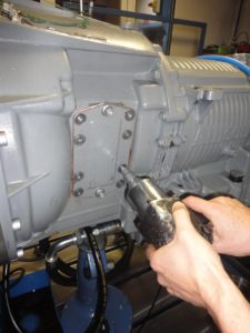
Remove the pto’s opening cover
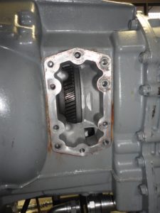
The transmission’s PTO drive gear and opening will be visible
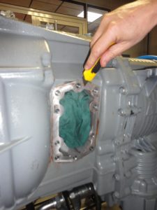
Clean the opening surface of adhesive or gasket residues. Be careful to avoid damages or scratches in the opening’s surface
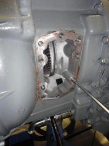
Fit the guide pins with a screwdriver.
Use loctite to avoid them from loosening
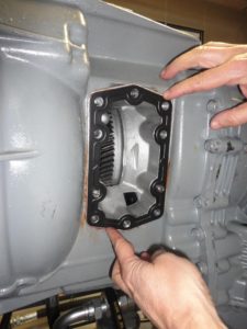
Place the steel gasket using a dab of grease, if necessary, to keep it in position. The ribbed surface should face towards the installer
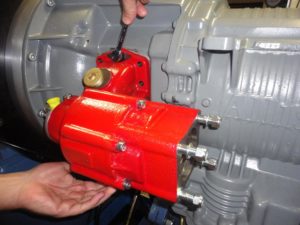
Fit at least one bolt/cap screw in each corner in each corner before checking the backlash
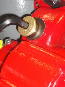
Unscrew the backlash check plug
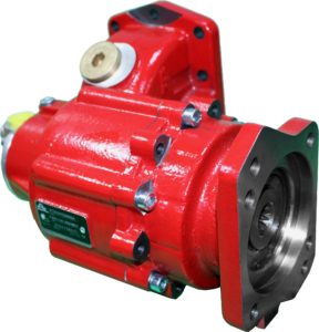
In case it is necessary to rotate the flange, coat the screws with Loctite 270. Tighten to 18-22 Lb.Ft. (25-30Nm)
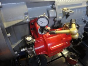
Check the appropriate backlash. It should be between 0.006” and 0.012”
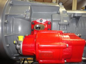
Tighten the remaining bolts at 44 – 50 lb.ft (60-68Nm)
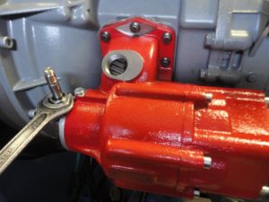
Install the cartridge and tighten to 25 – 30 Lb.ft (35 – 40 Nm).
Alternativelly, for easy installation, it can be installed on the pto before its being placed on the transmission

Place the coil. Ensure the O-ring is in place to avoid water leaks inside the coil.
Whenever it is used a metallic coil, o-rings from the cartridge are no longer needed.
Note: Place a small amount of Loctite Blue (243) on the aluminium nut that secures the coil.
Do not overtighten or the threads on the nut wil strip out.
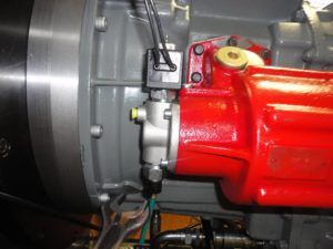
Install the pressure switch.
Alternativelly, for easy installation, it can be installed on the pto before it’s being placed on the transmission
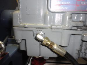
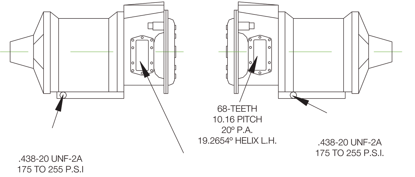
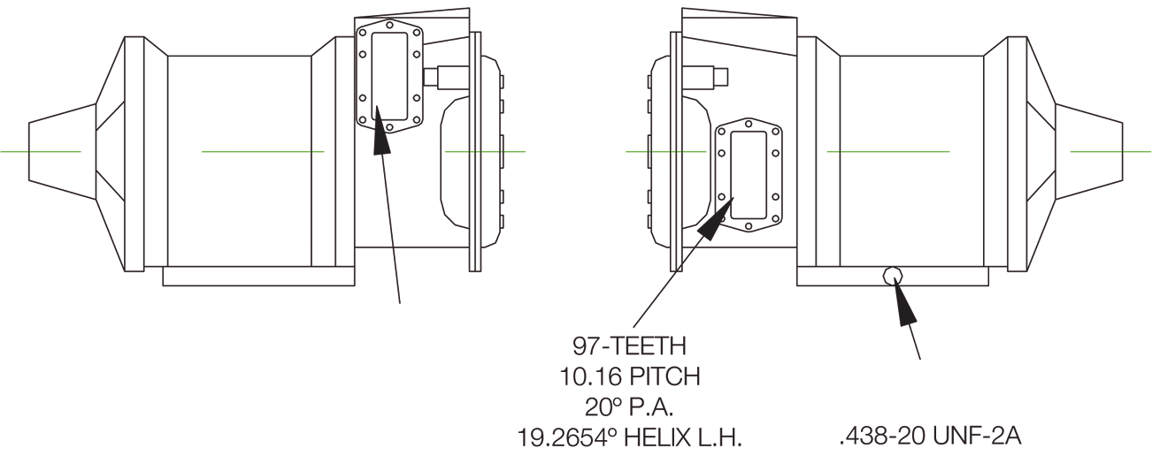
Install the fitting to transmission according to the suitable port specified in following section: “Pressure Port and Aperture Identification”, tight to 8 – 10 Lb. Ft. (11 – 14 Nm)
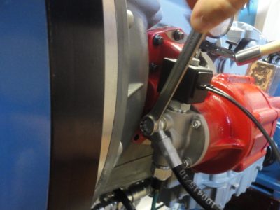
Install the other end of the the pressure line in the pto.
Tight to 12 – 14 Lb. Ft. (18 – 20 Nm)
- Remove the gearbox plug in position (A) and fit the connector supplied with the kit (1).
- Remove the protection plastic plug placed on the PTO (B).
- Fit the shifting hose (900899-2) on the (A) and (B) position by means of the hose (2) and fitting (3). Checking for proper oil level and signs of oil leakage, the best check is conducted with the transmission at operating temperature.
CAUTION
This vehicle is equipped with a Power Take-Off. Shut engine off before working on the Power Take-Off or getting below the vehicle.
Power Shift P.T.O.´s: The engine must be at idle or below 1000 RPM when the P.T.O. is engaged. See the transmission manufacturer’s instructions for special procedures.
Cold Weather Operation of Power Shift P.T.O.´s
- Driven equipment must have separate controls.
- Driven equipment must be left in the disengaged position when nor in operation.
- Driven equipment must not be operated until the vehicle is allowed to warm up.
IMPORTANT
Failures to follow proper shifting or operating sequences will result in premature P.T.O. failure with possible damage to other equipment.
Do not go under or near PTO when the engine is running. Shut off engine and disconnect
batteries on electric motor driven PTOs (i.e.: Hybrid vehicles) before checking or servicing.
The Power take-off, being an integral part of the transmission, should be serviced at the same intervals as the transmission. Transmission fluid changes should follow the interval recommended by the vehicle manufacturer for severe service.
Transmission oil level is important. Checking for PTO leaks and checking the transmission oil level should be done on a regular basis.
Check for leaks upon delivery of the vehicle and after initial operation of equipment. Loss of oil can significantly affect or damage transmissions.
Bezares USA is not responsible for damage resulting from improper fastener installation,
mounting torque or maintenance of PTO.
The Power Take-off may include the activation control parts, an auxiliary driveline device, or hydraulic pump. The PTO requires periodic checks. Typically the interval for maintenance checks of the PTO depends on the application of the vehicle. Every time the chassis is lubricated or a mechanic is under the vehicle the PTO should be checked. For severe duty PTO applications, it is recommended that the PTO be checked for service every 100 hours of use (this guideline can be adjusted based on past service history
once you have it established). Service should include checking and lubricating direct mount pump shaft connections on a regular basis. PTO gears can be checked for wear by removing the inspection or shifter cover. If pitting, galling, cracking, or deformation of the gears or splines has occurred, then the PTO needs to be rebuilt or replaced.
Within the first week of use, recheck the installation of the PTO. Check for leaks and
loose mounting hardware (studs, cap screws, nuts). Recheck the cable or lever connections for proper adjustment and tighten any loose connections. At regular maintenance intervals, check adjustments and lubricate moving parts, tighten and repair the connections, mounting hardware, cable or lever linkages.
It is recommended that the operator/owner do a visual inspection for leaks under and around the vehicle and equipment before entering or starting the equipment on at least a weekly basis. Any leaks found should be corrected immediately.
Note: Above paragragh should also state (When using Hot shift or Air shift PTO’s check air and hydraulic connections for leaks and tightness) tighten as necessary.
Pumps that are directly mounted to the PTO output require the application of anti-seize or a high temperature, high pressure grease (unless the PTO is a wet spline option). Installer must apply this kind of grease on the PTO output shaft, once installed, before the mounting of the hydraulic pump. The purpose of this grease is to help make the PTO easier to service and to reduce the effects of fretting corrosion on the mating PTO and pump shafts. PTO’s under severe duty cycles and/or high torque requirements may require servicing of this pump shaft connection by periodically regreasing the shafts. Vehicles with low speed engines are also considered to be severe duty applications due to the inherent vibrations of the vehicles. Fretting corrosion cannot be stopped by greasing the shafts, it is only a deterrent. Wet spline PTO’s does not require servicing this connection.
Ask your equipment installer if you have this option.
Warranty: Failure to comply entirely with the provisions set forth in the appropriate Owner’s Manual will result in voiding of ALL Warranty consideration.

